HWPE Interface Protocols#
HWPE-Stream protocol#
The HWPE-Stream protocol is a simple protocol designed to move data between the various sub-components of an HWPE. As HWPEs are memory-based accelerators, streams are typically generated and consumed internally within the accelerator between fully synchronous devices. HWPE-Stream can cross between two clock domains using dual-clock FIFOs; handshakes still have to happen in a fully synchronous way. HWPE-Stream streams are directional, flowing from a source to a sink direction, using a two signal handshake and carrying a data payload. Fig. 2 and Table 1 report the signals used by the HWPE-Stream protocol.
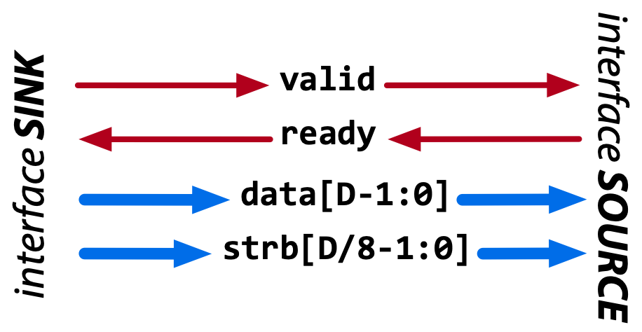
Fig. 2 Data flow of the HWPE-Stream protocol. Red signals carry the handshake, blue ones the payload.#
Signal |
Size |
Description |
Direction |
data |
Multiple of 8 bits |
The data payload transported by the stream. |
from source to sink |
strb |
size(data)/8 |
Optional. Indicates valid bytes in the data payload (1=valid). |
from source to sink |
valid |
1 bit |
Handshake valid signal (1=asserted). |
from source to sink |
ready |
1 bit |
Handshake ready signal (1=asserted). |
from sink to source |
The handshake signals valid and ready are used to validate transactions between sources and sinks. Transactions are subject to the following rules:
A handshake occurs in the cycle when both valid and ready are asserted. The handshake is the “atomic” event after which the current payload is considered consumed by the consumer at the sink side of the HWPE-Stream interface.
data and strb can change their value either a) when valid is deasserted, or b) in the cycle following a handshake, even if valid remains asserted. In other words, valid data payloads must stay on the interface until a valid handshake has occurred.
The assertion of valid (transition 0 to 1) cannot depend combinationally on the state of ready. On the other hand, the assertion of ready (transition 0 to 1) can depend combinationally on the state of valid. This rule, which is modeled around the similar behavior used by TCDM memories (see below) is meant to avoid any deadlock in ping-pong logic.
The deassertion of valid (transition 1 to 0) can happen only in the cycle after a valid handshake. In other words, valid data produced by a source must be correctly consumed before valid is deasserted.
wavedrom_hwpe_stream shows several correct handshakes on
a HWPE-Stream, while wavedrom_hwpe_stream_r2_no and
wavedrom_hwpe_stream_r4_no show two examples of incorrect
transactions. Both behaviors are checked by means of asserts in the
reference SystemVerilog code for HWPE-Stream interfaces.
Rule 3 cannot be checked by means of asserts; it is up to the designer
to avoid valid to ready combinational dependencies that could
result in combinational loops, since the value of ready is assumed
to be combinationally dependent from valid.
The only side channel that can be included in an HWPE-Stream is strb, which is optionally used to signal which bytes of the data payload contain meaningful data. HWPE-Stream streams in which strb is absent are assumed to have only valid bytes in their data payload. We refer HWPE-Stream streams with strb as strobed streams.
HWPE-Mem and HCI-Core protocols#
HWPE-Mem#
HWPEs are connected to external L1/L2 shared-memory by means of a simple memory protocol, using a request/grant handshake. The protocol used is called HWPE Memory (HWPE-Mem) protocol, and it is essentially similar to the protocol used by cores and DMAs operating on memories in standard PULP clusters. This document focuses on the specific signal names used within HWPEs and in the reference implementation of HWPE-Stream IPs. It supports neither multiple outstanding transactions nor bursts, as HWPEs using this protocol are assumed to be closely coupled to memories. It uses a two signal handshake and carries two phases, a request and a response.
The HWPE-Mem protocol is used to connect a master to a slave. Fig. 3 and Table 2 report the signals used by the HWPE-Mem protocol.
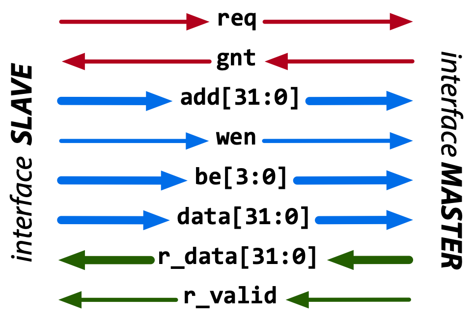
Fig. 3 Data flow of the HWPE-Mem protocol. Red signals carry the handshake; blue signals the request phase; green signals the response phase.#
Signal |
Size |
Description |
Direction |
req |
1 bit |
Handshake request signal (1=asserted). |
master to slave |
gnt |
1 bit |
Handshake grant signal (1=asserted). |
slave to master |
add |
32 bit |
Word-aligned memory address. |
master to slave |
wen |
1 bit |
Write enable signal (1=read, 0=write). |
master to slave |
be |
4 bit |
Byte enable signal (1=valid byte). |
master to slave |
data |
32 bit |
Data word to be stored. |
master to slave |
r_data |
32 bit |
Loaded data word. |
slave to master |
r_valid |
1 bit |
Valid loaded data word (1=asserted). |
slave to master |
The handshake signals req and gnt are used to validate transactions between masters and slaves. Transactions are subject to the following rules:
A valid handshake occurs in the cycle when both req and gnt are asserted. This is true for both write and read transactions.
r_valid must be asserted the cycle after a valid read handshake; r_data must be valid on this cycle. This is due to the tightly-coupled nature of memories; if the memory cannot respond in one cycle, it must delay granting the transaction.
The assertion of req (transition 0 to 1) cannot depend combinationally on the state of gnt. On the other hand, the assertion of gnt (transition 0 to 1) can depend combinationally on the state of req (and typically it does). This rule avoids deadlocks in ping-pong logic.
The semantics of the r_valid signal are not well defined with respect to the usual TCDM protocol. In PULP clusters, r_valid will be asserted also after write transactions, not only in reads. However, the HWPE-Mem protocol and the IPs in this repository should not make assumptions on the r_valid in write transactions.
HWPE-MemDecoupled#
The HWPE-Mem protocol can be used to directly connect an accelerator to the shared memory of a PULP-based system. However, transactions using this protocol are inherently latency sensitive. HWPE-Mem rule 2 embodies this: an operation is complete only when its response has arrived. This means that HWPE-Mem streams, including load and store transactions, cannot be enqueued in a FIFO queue. To overcome this limitation, a variant of the HWPE-Mem protocol is HWPE-MemDecoupled. This protocol uses the same interface as HWPE-Mem but lifts rule 2 and adds a new rule 4. Transactions are thus following the following rules:
A valid handshake occurs in the cycle when both req and gnt are asserted. This is true for both write and read transactions.
The assertion of req (transition 0 to 1) cannot depend combinationally on the state of gnt. On the other hand, the assertion of gnt (transition 0 to 1) can depend combinationally on the state of req (and typically it does). This rule avoids deadlocks in ping-pong logic.
The stream of transactions includes only reads ( wen =1) or only writes ( wen =0). Mixing reads and writes in the stream is not allowed.
HWPE-MemDecoupled transactions are insensitive to latency and their request and response phases can be treated similarly to separate HWPE-Stream streams. Once two or more HWPE-MemDecoupled transactions are mixed, the mixed interface has to be treated as a HWPE-Mem protocol (i.e. it is sensitive to latency).
HCI-Core#
HCI-Core (Heterogeneous Cluster Interconnect – Core) is a protocol designed as a lighteweight extension of HWPE-Mem better suited for the needs of accelerators, and specifically of cluster-coupled HWPEs. This document focuses on the specific signal names used within HWPEs and in the reference implementation of HCI IPs. HCI-Core does not support bursts, but it supports in-order multiple outstanding transactions in a similar fashion to HWPE-MemDecoupled. Differently from HWPE-Mem, HCI-Core uses a two signal handshake on the request phase and a separate two signal handshake on the response phase (r_valid / r_ready), enabling load backpressure on the response. HCI-Core also carries an optional ID side channel (id / r_id) that can be used to distinguish in-flight transactions when traversing HCI interconnects, and an optional ECC side channel (see Optional ECC side channel) to protect data and handshake signals. HCI-Core carries two phases, a request and a response. HCI-Core signals have parametric width; Table 3 reports the parameters used by the HCI IPs; while Table 4 reports the signals used by the HCI-Core protocol.
Parameter |
Description |
Default |
Range |
DW |
Data width in bits |
32 |
mult. of BW |
AW |
Address width in bits |
32 |
1-32 |
BW |
Width of an individually strobed “byte” in bits |
8 |
1-32 |
UW |
User-defined side-channel width in bits |
0 |
0-any |
IW |
Transaction ID width in bits |
8 |
0-any |
Signal |
Size |
Phase |
Description |
Direction |
req |
1 bit |
Request HS |
Request valid (1=asserted). |
master to slave |
gnt |
1 bit |
Request HS |
Request granted (1=asserted). |
slave to master |
r_valid |
1 bit |
Response HS |
Response valid (1=asserted). Mandatory for load, optional for stores. |
slave to master |
r_ready |
1 bit |
Response HS |
Response ready (1=asserted). Enables backpressure on the response. |
master to slave |
add |
AW bit |
Request |
Word-aligned memory address. |
master to slave |
wen |
1 bit |
Request |
Write enable signal (1=read, 0=write). |
master to slave |
be |
DW/BW bit |
Request |
Byte enable signal (1=valid byte). |
master to slave |
data |
DW bit |
Request |
Data word to be stored. |
master to slave |
user |
UW bit |
Request |
User-defined request side channel. |
master to slave |
id |
IW bit |
Request |
Transaction identifier (request). |
master to slave |
r_data |
DW bit |
Response |
Loaded data word. |
slave to master |
r_user |
UW bit |
Response |
User-defined response side channel. |
slave to master |
r_id |
IW bit |
Response |
Transaction identifier (response, echoed from id). |
slave to master |
r_opc |
1 bit |
Response |
Error code response. |
slave to master |
The two phases of HCI-Core transactions can be treated as two separate channels, so HCI-Core transactions can be latency insensitive and support multiple in-order outstanding transactions (i.e., pipeline transactions). Request and response phases are organized to be treated like HWPE-Stream streams. Table 5 and Table 6 detail the rules that have to be followed for a valid transaction.
Rule |
Description |
RQ-1 HANDSHAKE |
A valid handshake occurs in the cycle when both req and gnt are asserted, for both write and read transactions. All request phase signals are sampled on handshake cycles. |
RQ-2 NODEADLOCK |
The assertion of req (transition 0 to 1) cannot depend combinationally on the state of gnt. On the other hand, the assertion of gnt (transition 0 to 1) can depend combinationally on the state of req. This rule avoids deadlocks in ping-pong logic. |
RQ-3 STABILITY |
Request phase signals can change their value either in the cycle following a handshake, regardless if req is deasserted or stays asserted. |
RQ-OPT-3 NORETIRE |
(Optional) Requests cannot be retired after req is asserted. HCI accelerators satisfy this indication, but not all masters on HCI interconnects might be fully compliant. |
Rule |
Description |
RSP-1 HANDSHAKE |
For read transactions, a valid handshake occurs in the cycle when both r_valid and r_ready are asserted. All response phase signals are sampled on handshake cycles. |
RSP-2 NODEADLOCK |
The assertion of r_valid (transition 0 to 1) cannot depend combinationally on the state of r_ready. On the other hand, the assertion of r_ready (transition 0 to 1) can depend combinationally on the state of r_valid. This rule avoids deadlocks in ping-pong logic. |
RSP-3 STABILITY |
Response phase signals can change their value either in the cycle following a handshake, regardless if r_valid is deasserted or stays asserted. |
RSP-4 ORDERING |
Response phase signals must follow the same ordering of the requests. |
Optional ECC side channel#
The HCI-Core interface optionally exposes Error-Correcting Code (ECC) side channels to protect both the data payload and the handshake signals. These signals are always present in the interface, but are functionally inert (zero-width) when the corresponding parameters are left at their default value of 0. They are intended for use in safety- or reliability-critical deployments where end-to-end protection of HCI transactions is required.
Table 7 reports the additional parameters that control the ECC side channels, while Table 8 reports the related signals.
Parameter |
Description |
Default |
Range |
EW |
ECC width for the data payload in bits |
0 |
0-any |
EHW |
ECC width for the handshake signals in bits |
0 |
0-any |
Signal |
Size |
Phase |
Description |
Direction |
ecc |
EW bit |
Request data |
ECC bits protecting the request data payload. |
master to slave |
r_ecc |
EW bit |
Response data |
ECC bits protecting the response r_data payload. |
slave to master |
ereq |
EHW bit |
Request HS |
ECC bits protecting the req handshake signal. |
master to slave |
egnt |
EHW bit |
Request HS |
ECC bits protecting the gnt handshake signal. |
slave to master |
r_evalid |
EHW bit |
Response HS |
ECC bits protecting the r_valid handshake. |
slave to master |
r_eready |
EHW bit |
Response HS |
ECC bits protecting the r_ready handshake. |
master to slave |
When EW and EHW are set to 0, the ECC signals collapse to zero-width and have no functional effect; the interface then behaves identically to a plain HCI-Core interface.
wavedrom_hci_core shows an example of a correct HCI-Core transaction.
The request and response phases handshake independently: request phase signals
are sampled when req and gnt are both asserted, while response phase
signals are sampled when r_valid and r_ready are both asserted. This
decoupling enables multiple outstanding transactions and load backpressure
on the response, while rule RSP-4 (ORDERING) ensures that responses are
delivered in the same order as the corresponding requests.
Exchanging data between HCI-Core and HWPE-Stream#
As HWPEs ultimately consume and produce data to the external shared memory using one or more ports exposing HCI-Core (or, in legacy designs, HWPE-Mem) interfaces, converting data between HCI-Core and HWPE-Stream (i.e., exchanging data between the memory-based and the stream-based worlds) is one of the main tasks to be accomplished in the design of an accelerator. The HWPE-Stream and HCI-Core protocols are similar by design — both organize transactions around independent request and response handshakes that follow HWPE-Stream-like rules — which makes the handling of handshakes significantly easier. The following applies to HCI-Core, HWPE-MemDecoupled, and HWPE-Mem in a similar manner.
Three objectives have to be met:
HWPE-Stream has no notion of address: to produce a stream out of HCI-Core loads, or consume a stream in a series of HCI-Core stores, it is necessary to generate addresses according to some rule.
HWPE-Stream streams can be wider than the HCI-Core DW data width; it is necessary to generate them from / split them into multiple HCI-Core loads/stores.
HCI-Core addresses may be misaligned with respect to word boundaries, in which case two HCI-Core loads/stores are necessary to transact a single data word and strobes have to be also aligned.
In the current version of the HWPE specifications, we address these issues by providing a set of modules which can incrementally be used to solve each of the problems above. This are referred to in a later section.
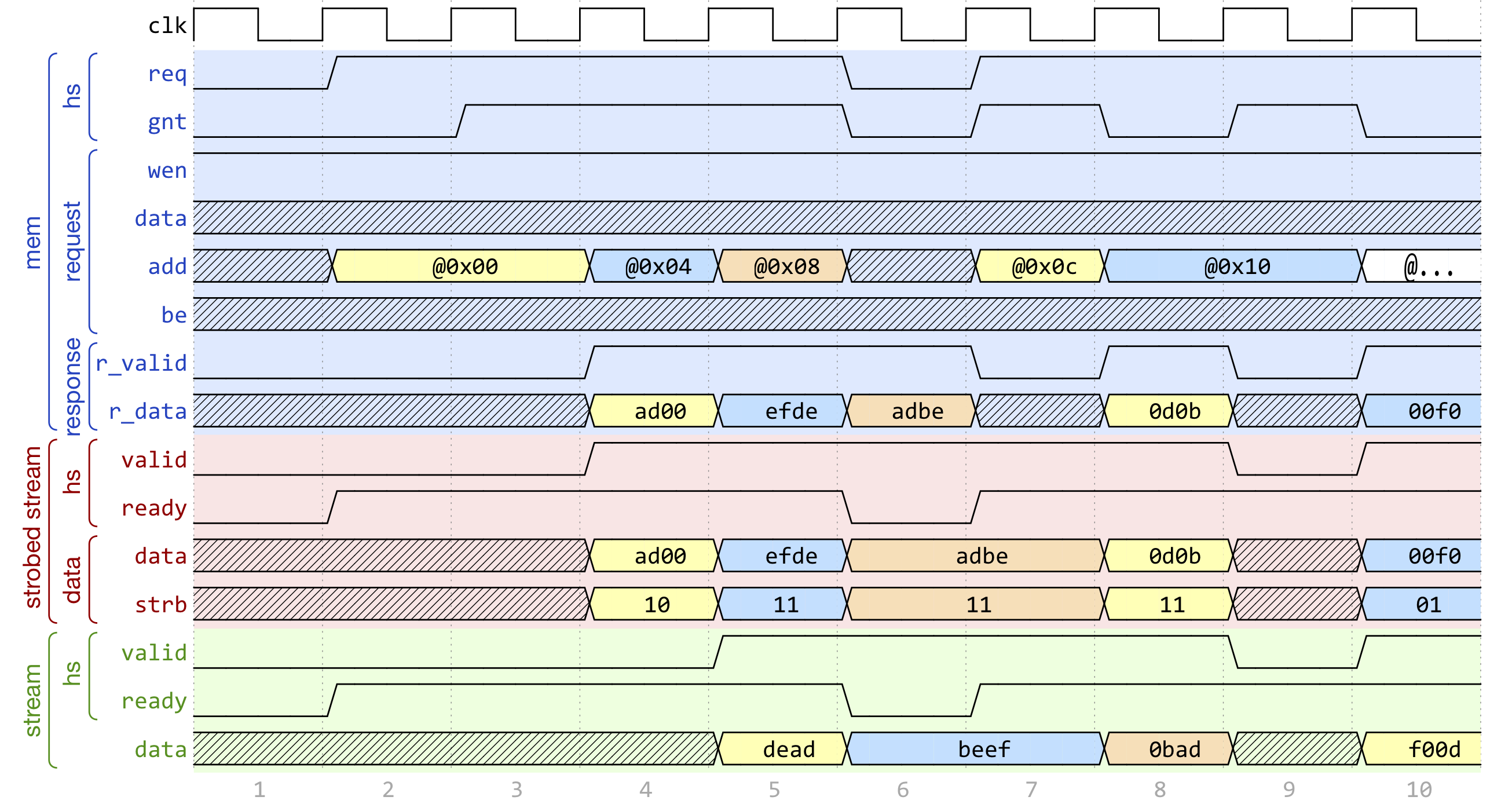
Fig. 4 Example of data exchange between a series of HCI-Core loads and a HWPE-Stream. Four data packets have to be produced at the sink end of the stream; since data is not well aligned in memory, this results in five loads on the HCI-Core interface, which are then transformed in a strobed HWPE-Stream. The stream is then realigned so that the correct four elements are available.#
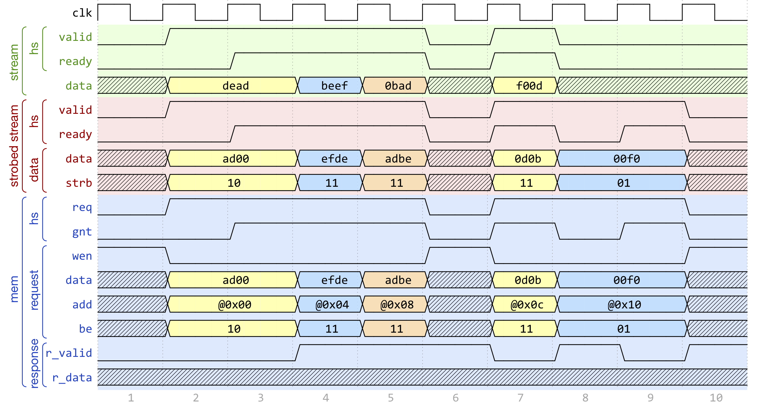
Fig. 5 Example of data exchange between a HWPE-Stream and a series of HCI-Core stores. Four data packets have to be consumed at the source end of the stream; since data is not well aligned in memory, this results in a strobed HWPE-Stream with five packets, the first and last of which contain also null data. The strobed stream is then converted in a set of five HCI-Core store transactions.#
Fig. 4, Fig. 5 show two examples of transactions going (respectively) from a series of loads on the HCI-Core interface to internal HWPE-Streams and from an internal HWPE-Stream to a series of stores on HCI-Core. The example focuses on the realignment behavior.
HWPE-Periph protocol#
To enable control, HWPEs typically expose a slave port to the peripheral system interconnect. The slave port follows an extension of the HWPE-Mem protocol which we call HWPE-Periph in this document. The HWPE-Periph protocol is essentially the same one exposed by most peripherals in a PULP system and used by the core to communicate with them.
Signal |
Size |
Description |
Direction |
req |
1 bit |
Handshake request signal (1=asserted). |
master to slave |
gnt |
1 bit |
Handshake grant signal (1=asserted). |
slave to master |
add |
32 bit |
Word-aligned memory address. |
master to slave |
wen |
1 bit |
Write enable signal (1=read, 0=write). |
master to slave |
be |
4 bit |
Byte enable signal (1=valid byte). |
master to slave |
data |
32 bit |
Data word to be stored. |
master to slave |
id |
ID_WIDTH bits |
ID used to identify the master (request). |
master to slave |
r_data |
32 bit |
Loaded data word. |
slave to master |
r_valid |
1 bit |
Valid loaded data word (1=asserted). |
slave to master |
r_id |
ID_WIDTH bits |
ID used to identify the master (reply). |
slave to master |
The HWPE-Periph protocol is distinguished by the HWPE-Mem protocol by the id and r_id side channels. These are used in load operations issued through a PERIPH interface: the id identifies the master during the request phase, is buffered by the slave peripherals and accompanies the response phase as r_id. In this way, multiple masters can distinguish which traffic is related to themselves. For the rest of the purposes related with HWPEs, HWPE-Periph and HWPE-Mem work in the same way. In particular, similarly to HWPE-Mem, PULP clusters will expect r_valid to be asserted after write transactions. This is enforced also in HWPE IPs.