Hardware Processing Engines: Concept and IPs#
Hardware Processing Engines (HWPEs) are special-purpose, memory-coupled accelerators that can be inserted in the SoC or cluster of a PULP system to amplify its performance and energy efficiency in particular tasks.
Differently from most accelerators in literature, HWPEs do not rely on an external DMA to feed them with input and to extract output, and they are not (necessarily) tied to a single core. Rather, they operate directly on the same memory that is shared by other elements in the PULP system (e.g. the L1 TCDM in a PULP cluster, or the shared L2 in PULPissimo). Their control is memory-mapped and accessed through a peripheral bus or interconnect. HW-based execution on an HWPE can be readily intermixed with software code, because all that needs to be exchanged between the two is a set of pointers and, if necessary, a few parameters.
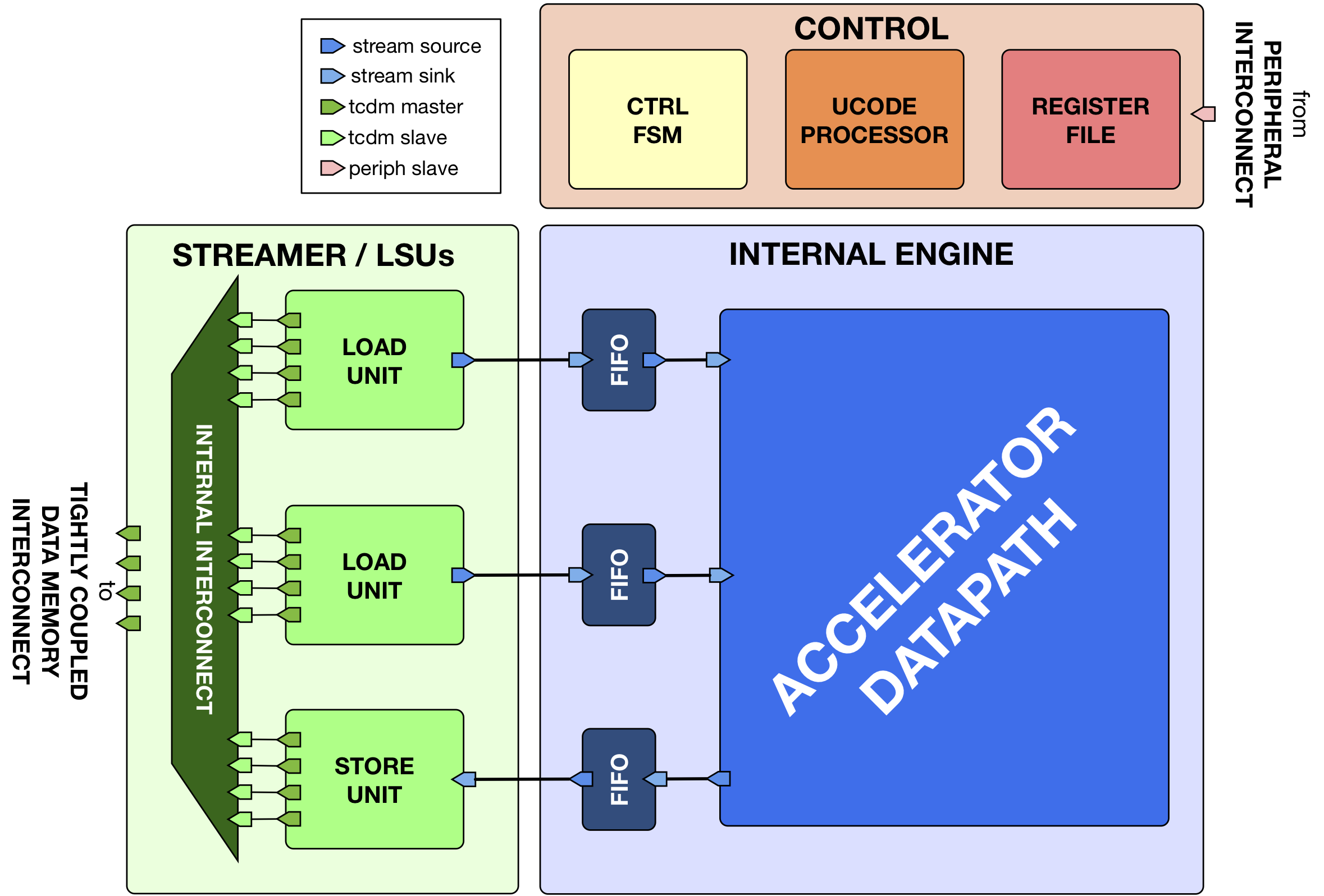
Fig. 6 Template of a Hardware Processing Engine (HWPE).#
This document defines the interface protocols and modules that are used to enable connecting HWPEs in a PULP system. Typically, such a module is divided in a streamer interface towards the memory system, a control/peripheral interface used for programming it, and an engine containing the actual datapath of the accelerator.
HWPE Interface Modules: Data Movement & Marshaling#
Basic modules (HWPE-Stream)#
Basic HWPE-Stream management modules are used to select multiple streams, merge multiple streams into one, split a stream in multiple ones, synchronize their handshakes and similar basic “morphing” functionality; or to delay and enqueue streams. Modules performing these functions can be found within the rtl/basic and rtl/fifo subfolders of the hwpe-stream repository.
hwpe_stream_merge#

The hwpe_stream_merge module is used to merge NB_IN_STREAMS input streams into a single, bigger stream. The data and strb channels from the input streams are bound in order and the valid is generated as the AND of all valid’s from input streams. The ready is broadcasted from the output stream to all input streams.
A typical use of this module is to take NB_IN_STREAMS 32-bit streams coming from a TCDM load interface to be merged into a single bigger stream.
The following shows an example of the hwpe_stream_merge operation:
Name |
Default |
Description |
NB_IN_STREAMS |
2 |
Number of input HWPE-Stream streams. |
DATA_WIDTH_IN |
32 |
Width of the input HWPE-Stream streams. |
hwpe_stream_split#
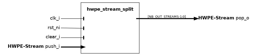
The hwpe_stream_split module is used to split a single stream into NB_OUT_STREAMS, 32-bit output streams. The data and strb channel from the input stream is split in ordered output streams, and the valid is broadcast to all outgoing streams. The ready is generated as the AND of all ready’s from output streams.
A typical use of this module is to take a multiple-of-32-bit stream coming from within the HWPE and split it into multiple 32-bit streams that feed a TCDM store interface.
The following shows an example of the hwpe_stream_split operation:
Name |
Default |
Description |
NB_OUT_STREAMS |
2 |
Number of output HWPE-Stream streams. |
DATA_WIDTH_IN |
128 |
Width of the input HWPE-Stream stream. |
hwpe_stream_fence#
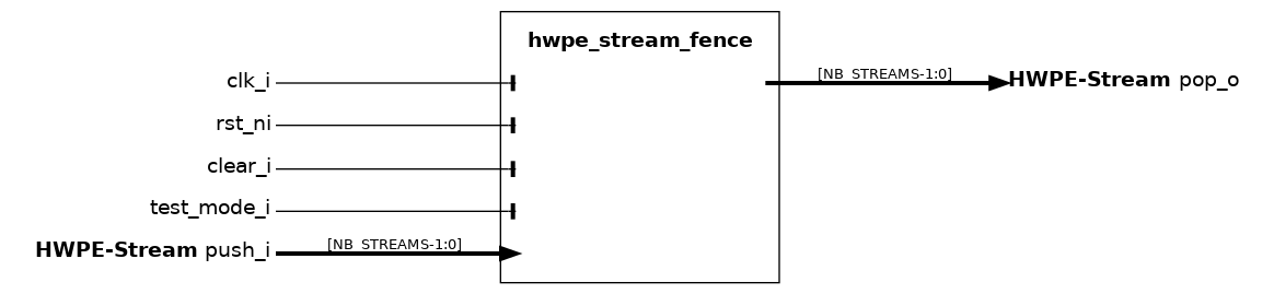
The hwpe_stream_fence module is used to synchronize the handshake between NB_STREAMS streams. This is necessary, for example, when multiple 32-bit streams are produced from separate TCDM accesses and have to be joined into a single, wider stream.
Name |
Default |
Description |
NB_STREAMS |
2 |
Number of input/output HWPE-Stream streams. |
DATA_WIDTH |
32 |
Width of the HWPE-Stream streams. |
hwpe_stream_mux_static#
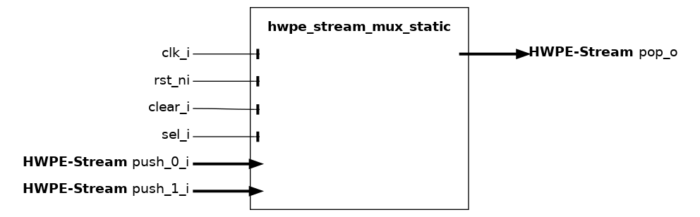
The hwpe_stream_mux_static module is used to statically propagate one of 2 input streams of size DATA_SIZE into a single output stream. The multiplexer is static as the selection bit sel_i cannot be changed when there are transactions in flight; if the selection bit is changed when transactions are in flight, the result is undefined.
The following shows an example of the hwpe_stream_mux_static operation:
hwpe_stream_demux_static#
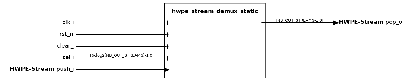
The hwpe_stream_demux_static module is used to propagate a single input stream of size DATA_SIZE into one of NB_OUT_STREAMS output streams. The non-selected output streams are all invalid. The demultiplexer is static as the selection bit sel_i cannot be changed when there are transactions in flight; if the selection bit is changed when transactions are in flight, the result is undefined.
The following shows an example of the hwpe_stream_demux_static operation:
Name |
Default |
Description |
NB_OUT_STREAMS |
2 |
Number of output HWPE-Stream streams. |
hwpe_stream_fifo#
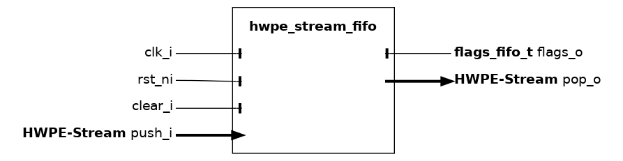
The hwpe_stream_fifo module implements a hardware FIFO queue for HWPE-Stream streams, used to withstand data scarcity (valid`=0) or backpressure (`ready`=0), decoupling two architectural domains. This FIFO is single-clock and therefore cannot be used to cross two distinct clock domains. The FIFO will lower its `ready signal on the input stream push_i interface when it is completely full, and will lower its valid signal on the output stream pop_o interface when it is completely empty. The regular FIFO does not allow for transactions to fall through the FIFO queue if there are no stalls, therefore any transaction always “pays” at least 1 cycle latency through the FIFO. The alternative is the passthrough FIFO hwpe_stream_fifo_passthrough.
Name |
Default |
Description |
DATA_WIDTH |
32 |
Width of the HWPE-Streams (typically multiple of 32, but this module does not care). |
FIFO_DEPTH |
8 |
Depth of the FIFO queue (multiple of 2). |
LATCH_FIFO |
0 |
If 1, use latches instead of flip-flops (requires special constraints in synthesis). |
LATCH_FIFO_TEST_WRAP |
0 |
If 1 and LATCH_FIFO is 1, wrap latches with BIST wrappers. |
Name |
Type |
Description |
empty |
logic |
1 if the FIFO is currently empty. |
full |
logic |
1 if the FIFO is currently full. |
push_pointer |
logic[7:0] |
Unused. |
pop_pointer |
logic[7:0] |
Unused. |
hwpe_stream_fifo_passthrough#
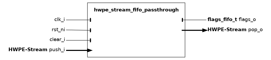
The hwpe_stream_fifo_passthrough module implements a hardware FIFO queue for HWPE-Stream streams, used to withstand data scarcity (valid`=0) or backpressure (`ready`=0), decoupling two architectural domains. This FIFO is single-clock and therefore cannot be used to cross two distinct clock domains. The FIFO will lower its `ready signal on the input stream push_i interface when it is completely full, and will lower its valid signal on the output stream pop_o interface when it is completely empty. The passthrough FIFO allows for transactions to fall through the FIFO queue (with 0 latency) if there are no stalls. This has the advantage to minimize latency, at the cost of not cutting combinational paths. The alternative is the regular FIFO hwpe_stream_fifo.
Name |
Default |
Description |
DATA_WIDTH |
32 |
Width of the HWPE-Streams (typically multiple of 32, but this module does not care). |
FIFO_DEPTH |
8 |
Depth of the FIFO queue (multiple of 2). |
LATCH_FIFO |
0 |
If 1, use latches instead of flip-flops (requires special constraints in synthesis). |
LATCH_FIFO_TEST_WRAP |
0 |
If 1 and LATCH_FIFO is 1, wrap latches with BIST wrappers. |
Name |
Type |
Description |
empty |
logic |
1 if the FIFO is currently empty. |
full |
logic |
1 if the FIFO is currently full. |
push_pointer |
logic[7:0] |
Unused. |
pop_pointer |
logic[7:0] |
Unused. |
hwpe_stream_fifo_earlystall#
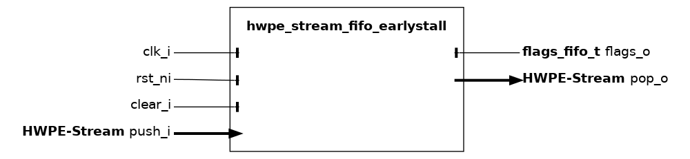
The hwpe_stream_fifo_earlystall module implements a hardware FIFO queue for HWPE-Stream streams, used to withstand data scarcity (valid =1) or backpressure (ready =1), decoupling two architectural domains. This FIFO is single-clock and therefore cannot be used to cross two distinct clock domains. The only difference with respect to hwpe_stream_fifo is that this version of the FIFO lowers its ready signal one cycle earlier, i.e. when it is filled by FIFO_DEPTH -1 elements. It will lower its valid signal on the output stream pop_o interface when it is completely empty.
Name |
Default |
Description |
DATA_WIDTH |
32 |
Width of the HWPE-Streams (multiple of 32). |
FIFO_DEPTH |
8 |
Depth of the FIFO queue (multiple of 2). |
LATCH_FIFO |
0 |
If 1, use latches instead of flip-flops (requires special constraints in synthesis). |
Name |
Type |
Description |
empty |
logic |
1 if the FIFO is currently empty. |
full |
logic |
1 if the FIFO is currently full. |
push_pointer |
logic[7:0] |
Unused. |
pop_pointer |
logic[7:0] |
Unused. |
hwpe_stream_fifo_ctrl#
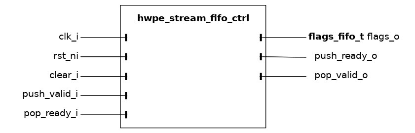
The hwpe_stream_fifo_ctrl module implements a hardware FIFO queue similar to that implemented by hwpe_stream_fifo, but without any actual interface handshake forced on HWPE-Streams. Instead, it will push its “virtual” handshake on the push_valid_i/push_ready_o and pop_valid_o/pop_ready_i signals. It can be used to operate multiple big FIFO queues (e.g. with latches) in a synchronized fashion without breaking the HWPE-Stream protocol.
Name |
Default |
Description |
FIFO_DEPTH |
8 |
Depth of the FIFO queue (multiple of 2). |
HCI Core modules#
hci_core_assign#

The hci_core_assign module implements a simple assignment for HCI-Core streams.
hci_core_assign_expand#

The hci_core_assign module implements a simple assignment for HCI-Core streams. This expand version cleanly expands the data width.
hci_core_cut#
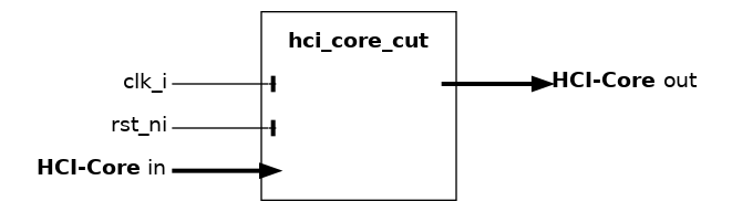
The hci_core_cut module implement a timing cut (pipeline register) on an HCI core interface. It inserts spill registers on both the request (initiator-to-target) and response (target-to-initiator) channels of an hci_core_intf, breaking long combinational paths to improve timing closure.
The cut is used in hci_interconnect and hci_ecc_interconnect to optionally decouple the core, DMA, and external ports from the interconnect fabric.
hci_core_fifo#

The hci_core_fifo module implements a hardware FIFO queue for HCI-Core interfaces, used to withstand data scarcity (req=0) or backpressure (gnt=0), decoupling two architectural domains. This FIFO is single-clock and therefore cannot be used to cross two distinct clock domains. The FIFO treats a HCI-Core load stream as a combination of two 32-bit HWPE-Streams, one going from the tcdm_initiator to the tcdm_target interface carrying the addr (outgoing stream); the other from the tcdm_target to the tcdm_initiator interface, carrying the r_data (incoming stream).
On the target side, the req and gnt of the HCI-Core interfaces
are mapped on valid and ready respectively in the outgoing stream.
Backpressure on the incoming stream (target side) cannot be enforced by means
of the HCI-Core target interface and thus is carried by a specific
input ready_i that must be generated outside of the TCDM FIFO, typically
by a hwpe_stream_source module (output tcdm_fifo_ready_o).
On the initiator side, req is mapped to the AND of the incoming stream ready
signal and the outgoing stream valid signal. gnt is hooked to the
outgoing stream ready signal.
The r_valid is mapped on valid in the incoming stream.
_hci_core_fifo_mapping shows this mapping.
Mapping of HCI-Core and HWPE-Stream signals inside the load FIFO.
Name |
Default |
Description |
FIFO_DEPTH |
8 |
Depth of the FIFO queue (multiple of 2). |
LATCH_FIFO |
0 |
If 1, use latches instead of flip-flops (requires special constraints in synthesis). |
Name |
Type |
Description |
empty |
logic |
1 if the FIFO is currently empty. |
full |
logic |
1 if the FIFO is currently full. |
push_pointer |
logic[7:0] |
Unused. |
pop_pointer |
logic[7:0] |
Unused. |
hci_core_mux_dynamic#
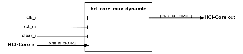
The HCI multiplexer can be used to funnel more input “virtual” HCI channels in into a smaller set of initiator ports out. It uses a round robin counter to avoid starvation, and differs from the modules used within the logarithmic interconnect in that arbitration is performed depending on the round robin counter and not on the target port; in other words, its task is to fill all out ports with requests from the in port, and not to route in requests to a specific out port.
Notice that the multiplexer is not “optimal” in the sense that there is no reorder buffer, so transactions cannot be swapped in-flight to optimally fill the downstream available bandwidth. However, in real accelerators many systematic issues with bandwidth sharing can be solved by upstream HCI FIFOs and by clever reordering of channels, since the dataflow schedule is known. For a multiplexer with reorder buffer, see hci_core_mux_ooo.
Name |
Default |
Description |
NB_IN_CHAN |
2 |
Number of input HWPE-Mem channels. |
NB_OUT_CHAN |
1 |
Number of output HWPE-Mem channels. |
hci_core_mux_ooo#
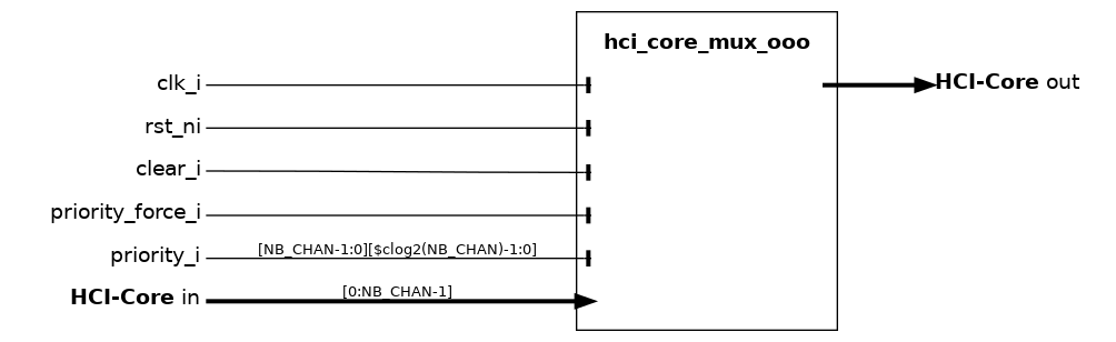
The HCI dynamic OoO N-to-1 multiplexer enables to funnel multiple HCI ports into a single one. It supports out-of-order responses by means of ID. As the ID is implemented as user signal, any FIFO coming after (i.e., nearer to memory side) with respect to this block must respect id signals - specifically it must return them identical in the response. At the end of the chain, there will typically be a hci_core_r_id_filter block reflecting back all the IDs. This must be placed at the 0-latency boundary with the memory system. Priority is normally round-robin but can also be forced from the outside by setting priority_force_i to 1 and driving the priority_i array to the desired priority values.
Name |
Default |
Description |
NB_CHAN |
2 |
Number of input HCI channels. |
hci_core_mux_static#
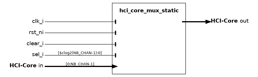
The HCI static multiplexer can be used in place of the dynamic ones when two sets of ports are guaranteed to be used in a strictly alternative fashion.
Name |
Default |
Description |
NB_CHAN |
2 |
Number of input HCI channels. |
hci_core_rob#
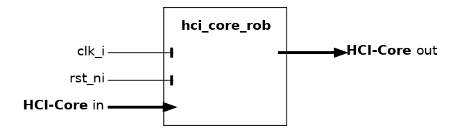
The HCI-Core reorder buffer issues requests with up to ROB_NW unique user-IDs. The responses can be retired out-of-order, by comparing the incoming response user-ID with the issued IDs. As the user-ID is implemented as user signal, any module coming after (i.e., nearer to memory side) with respect to this block must respect user signals - specifically it must return them identical in the response.
Name |
Default |
Description |
ROB_NW |
8 |
Number of supported outstanding transactions. |
hci_core_r_id_filter#
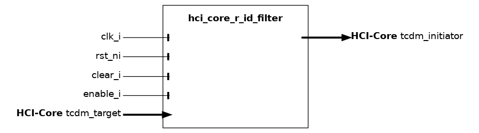
This block filters the id field of the TCDM request, and forwards it to the r_id field of the TCDM response.
hci_core_r_valid_filter#
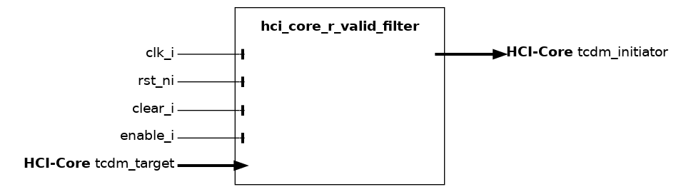
This block filters the r_valid field of the TCDM response: when enable_i is 1, only responses with r_valid=1 in case of a read transaction. The block is currently only working at the zero-latency boundary between core and memory (it expects that the latency between gnt and r_valid is exactly one cycle).
hci_core_split#
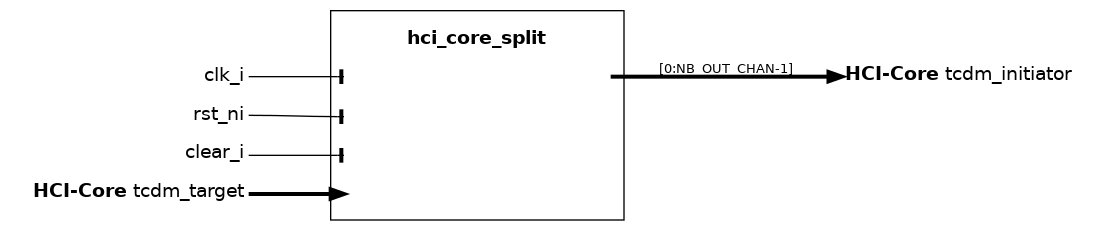
The hci_core_split module uses FIFOs to enqueue a split version of the HCI transactions. The FIFO queues evolve in a synchronized fashion on the accelerator side and evolve freely on the TCDM side. In this way, split transactions that can not be immediately brought back to the accelerator do not need to be repeated, massively reducing TCDM traffic. The hci_core_split requires to be followed (not preceded!) by any hci_core_r_id_filter that is used, for example, to implement HCI IDs for the purpose of supporting out-of-order access from a hci_core_mux.
Name |
Default |
Description |
NB_OUT_CHAN |
2 |
Number of output channels. |
FIFO_DEPTH |
0 |
Depth of internal HCI Core FIFOs. |
Connection to variable-latency interconnect (TeraPool systems)#
The following modules are used to provide an interface between HCI systems and systems using the variable-latency interconnect (typically in a TeraPool configuration).
hci_variablelatency_assign#

The hci_variablelatency_assign module implements a simple assignment for HCI-variablelatency streams.
hci_variablelatency_tocore#

The hci_variablelatency_tocore module implements a simple conversion for HCI-variablelatency streams.
Basic modules (HWPE-Mem / HWPE-MemDecoupled - deprecated)#
Basic HWPE-Mem management modules are used to delay/enqueue HWPE-MemDecoupled interfaces, multiplex multiple HWPE-Mem, or reorder them before hooking the accelerator to a Tightly-Coupled Data Memory (TCDM). Modules performing these functions can be found within the rtl/tcdm subfolder of the hwpe-stream repository.
hwpe_stream_tcdm_fifo_store#
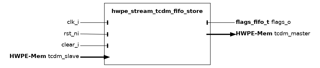
The hwpe_stream_tcdm_fifo_store module implements a hardware FIFO queue for
HWPE-MemDecoupled store streams, used to withstand data scarcity (req`=0) or
backpressure (`gnt`=0), decoupling two architectural domains.
This FIFO is single-clock and therefore cannot be used to cross two
distinct clock domains.
The FIFO treats a HWPE-MemDecoupled store stream as a wide HWPE-Stream where,
on both sides, the `data field contains addr, data, be of
the input tcdm_slave; the req and gnt of the HWPE-MemDecoupled
interfaces are mapped on valid and ready respectively.
The FIFO will lower its gnt signal on the slave interface tcdm_slave
when it is completely full, and will lower its req
signal on the master interface tcdm_master when it is completely
empty. _hwpe_stream_tcdm_fifo_store_mapping shows this mapping.
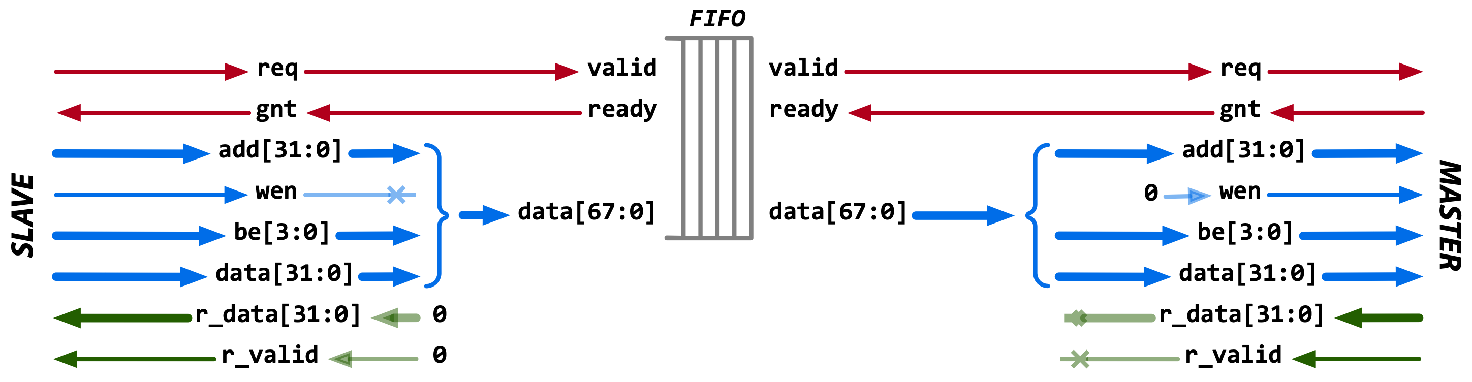
Fig. 7 Mapping of HWPE-MemDecoupled and HWPE-Stream signals inside the store FIFO.#
Name |
Default |
Description |
FIFO_DEPTH |
8 |
Depth of the FIFO queue (multiple of 2). |
LATCH_FIFO |
0 |
If 1, use latches instead of flip-flops (requires special constraints in synthesis). |
Name |
Type |
Description |
empty |
logic |
1 if the FIFO is currently empty. |
full |
logic |
1 if the FIFO is currently full. |
push_pointer |
logic[7:0] |
Unused. |
pop_pointer |
logic[7:0] |
Unused. |
hwpe_stream_tcdm_fifo_load#
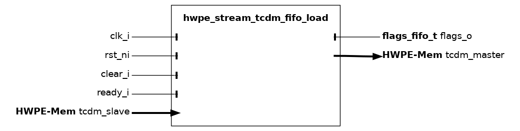
The hwpe_stream_tcdm_fifo_load module implements a hardware FIFO queue for HWPE-MemDecoupled load streams, used to withstand data scarcity (req`=0) or backpressure (`gnt`=0), decoupling two architectural domains. This FIFO is single-clock and therefore cannot be used to cross two distinct clock domains. The FIFO treats a HWPE-MemDecoupled load stream as a combination of two 32-bit HWPE-Streams, one going from the `tcdm_master to the tcdm_slave interface carrying the addr (outgoing stream); the other from the tcdm_slave to the tcdm_master interface, carrying the r_data (incoming stream).
On the slave side, the req and gnt of the HWPE-MemDecoupled interfaces
are mapped on valid and ready respectively in the outgoing stream.
Backpressure on the incoming stream (slave side) cannot be enforced by means
of the HWPE-MemDecoupled slave interface and thus is carried by a specific
input ready_i that must be generated outside of the TCDM FIFO, typically
by a hwpe_stream_source module (output tcdm_fifo_ready_o).
On the master side, req is mapped to the AND of the incoming stream ready
signal and the outgoing stream valid signal. gnt is hooked to the
outgoing stream ready signal.
The r_valid is mapped on valid in the incoming stream.
_hwpe_stream_tcdm_fifo_load_mapping shows this mapping.
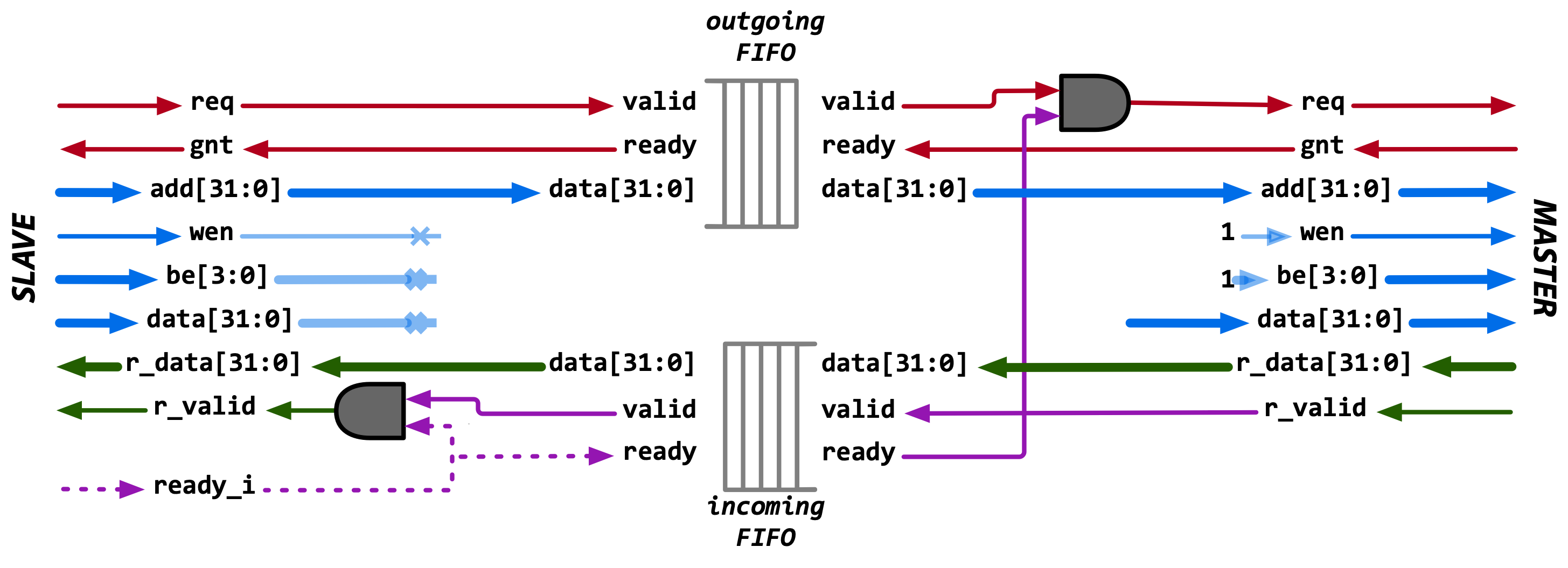
Fig. 8 Mapping of HWPE-MemDecoupled and HWPE-Stream signals inside the load FIFO.#
Name |
Default |
Description |
FIFO_DEPTH |
8 |
Depth of the FIFO queue (multiple of 2). |
LATCH_FIFO |
0 |
If 1, use latches instead of flip-flops (requires special constraints in synthesis). |
Name |
Type |
Description |
empty |
logic |
1 if the FIFO is currently empty. |
full |
logic |
1 if the FIFO is currently full. |
push_pointer |
logic[7:0] |
Unused. |
pop_pointer |
logic[7:0] |
Unused. |
hwpe_stream_tcdm_mux#
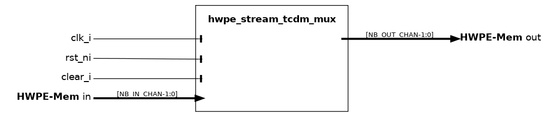
The TCDM multiplexer can be used to funnel more input “virtual” TCDM channels in into a smaller set of master ports out. It uses a round robin counter to avoid starvation, and differs from the modules used within the logarithmic interconnect in that arbitration is performed depending on the round robin counter and not on the slave port; in other words, its task is to fill all out ports with requests from the in port, and not to route in requests to a specific out port.
Notice that the multiplexer is not “optimal” in the sense that there is no reorder buffer, so transactions cannot be swapped in-flight to optimally fill the downstream available bandwidth. However, in real accelerators many systematic issues with bandwidth sharing can be solved by upstream TCDM FIFOs and by clever reordering of channels, since the dataflow schedule is known.
Name |
Default |
Description |
NB_IN_CHAN |
2 |
Number of input HWPE-Mem channels. |
NB_OUT_CHAN |
1 |
Number of output HWPE-Mem channels. |
hwpe_stream_tcdm_mux_static#
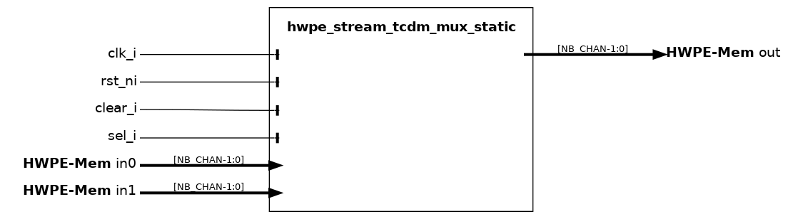
The hwpe_stream_tcdm_mux_static module is used to statically share a set of out master ports using the HWPE-Mem protocol between two sets of slave ports in0 and in1. It works similarly to the hwpe_stream_mux_static and similarly requires a strictly static selector sel_i.
Name |
Default |
Description |
NB_CHAN |
2 |
Number of output HWPE-Mem channels. |
hwpe_stream_tcdm_reorder#
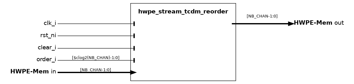
The hwpe_stream_tcdm_reorder block can be used to rotate the order of a set of HWPE-Mem channels depending on an order_i input, which can be changed dynamically (e.g. a counter). This is used to “equalize” channels with different probabilities of issuing a request so that the downstream HWPE-Mem channels are used with the same average probability, minimizing the chances for memory starvation.
Name |
Default |
Description |
NB_CHAN |
2 |
Number of HWPE-Mem channels. |
HCI Streamer modules#
Streamer modules constitute the heart of the IPs use to interface HWPEs with a PULP system. They include all the modules that are used to generate HWPE-Streams from address patterns on the TCDM, including the address generation itself, data realignment to enable access to data located at non-byte-aligned addresses, strobe generation to selectively disable parts of a stream, and the main streamer source and sink modules used to put these functions together. HCI Modules performing these functions can be found within the rtl/core subfolder of the hci repository.
Two main streamer modules (hci_core_source and hci_core_sink) are composite of several other IPs, including address generation and strobe generation blocks included in this section, as well as of basic HWPE-Stream management blocks.
hci_core_source#
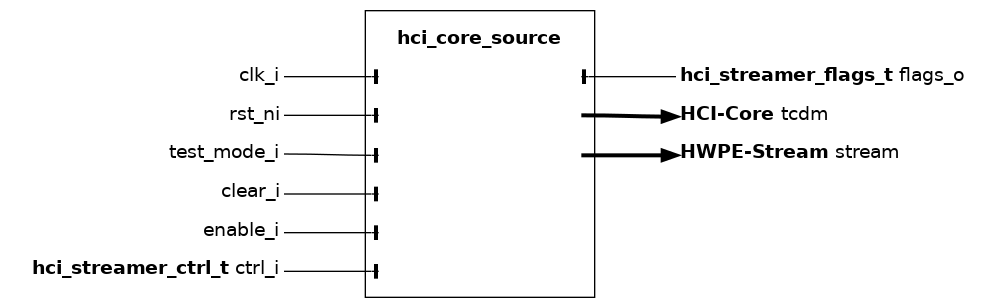
The hci_core_source module is the high-level source streamer performing a series of loads on a HCI-Core interface and producing a HWPE-Stream data stream to feed a HWPE engine/datapath. The source streamer is a composite module that makes use of many other fundamental IPs.
Fundamentally, a source streamer acts as a specialized DMA engine acting out a predefined pattern from an hwpe_stream_addressgen_v4 to perform a burst of loads via a HCI-Core interface, producing a HWPE-Stream data stream from the HCI-Core r_data field. By default, the HCI-Core streamer supports delayed accesses using a HCI-Core interface.
Misaligned accesses are supported by widening the HCI-Core data width by one memory-bank data width (BANK_DATA_WIDTH = ELEMENT_WIDTH * ELEMENTS_PER_BANK, 32 bits by default) compared to the HWPE-Stream that gets produced by the streamer. Unused bytes are simply ignored. This feature can be deactivated by unsetting the MISALIGNED_ACCESSES parameter; in this case, the source will only work correctly if all data is aligned to a bank-word boundary.
In principle, the source streamer is insensitive to latency. However, when configured to support misaligned memory accesses, the address FIFO depth sets the maximum supported latency. This parameter can be controlled by the ADDR_MIS_DEPTH parameter (default 8).
Name |
Default |
Description |
LATCH_FIFO |
0 |
If 1, use latches instead of flip-flops (requires special constraints in synthesis). |
TRANS_CNT |
16 |
Number of bits supported in the transaction counter of the address generator, which will overflow at 2^ TRANS_CNT. |
ADDR_MIS_DEPTH |
8 |
Depth of the misaligned address FIFO. This must be equal to the max-latency between the HCI-Core gnt and r_valid. |
MISALIGNED_ACCESSES |
1 |
If set to 0, the source will not support non-bank-word-aligned HCI-Core accesses. |
PASSTHROUGH_FIFO |
0 |
If set to 1, the address FIFO will be capable of fall-through operation (i.e., skipping the FIFO latency entirely). |
RESP_FIFO_DEPTH |
0 |
If > 0, responses are buffered through a HWPE-Stream FIFO of this depth before reaching the output stream. |
ELEMENT_WIDTH |
8 |
Bit-width of a single data element; with ELEMENTS_PER_BANK it sets the bank data width. |
ELEMENTS_PER_BANK |
4 |
Number of elements stored in one memory bank; sets the bank data width. |
DIM_ENABLE_1H |
4’b0011 |
Bit-mask selecting how many address-generator dimensions are enabled (see hwpe_stream_addressgen_v4). |
Name |
Type |
Description |
req_start |
logic |
When 1, the source streamer operation is started if it is ready. |
addressgen_ctrl |
ctrl_addressgen_v4_t |
Configuration of the address generator (see hwpe_stream_addressgen_v4). |
Name |
Type |
Description |
ready_start |
logic |
1 when the source streamer is ready to start operation, from the first IDLE state cycle on. |
done |
logic |
1 for one cycle when the streamer ends operation, in the cycle before it goes to IDLE state . |
addressgen_flags |
flags_addressgen_v4_t |
Address generator flags (see hwpe_stream_addressgen_v4). |
hci_core_source_v2#

The hci_core_source_v2 module is the high-level source streamer performing a series of loads on a HCI-Core interface and producing a HWPE-Stream data stream to feed a HWPE engine/datapath. The source streamer is a composite module that makes use of many other fundamental IPs.
Fundamentally, a source streamer acts as a specialized DMA engine acting out a predefined pattern from an hwpe_stream_addressgen_v3 to perform a burst of loads via a HCI-Core interface, producing a HWPE-Stream data stream from the HCI-Core r_data field. By default, the HCI-Core streamer supports delayed accesses using a HCI-Core interface.
Misaligned accesses are supported by widening the HCI-Core data width of 32 bits compared to the HWPE-Stream that gets produced by the streamer. Unused bytes are simply ignored. This feature can be deactivated by unsetting the MISALIGNED_ACCESS parameter; in this case, the sink will only work correctly if all data is aligned to a word boundary.
In principle, the source streamer is insensitive to latency. However, when configured to support misaligned memory accesses, the address FIFO depth sets the maximum supported latency. This parameter can be controlled by the ADDR_MIS_DEPTH parameter (default 8).
Compared to the hci_core_source module, the hci_core_source_v2 introduce a job queue to enqueue streamer jobs earlier and streamline/optimize ctrl.
Name |
Default |
Description |
LATCH_FIFO |
0 |
If 1, use latches instead of flip-flops (requires special constraints in synthesis). |
TRANS_CNT |
16 |
Number of bits supported in the transaction counter of the address generator, which will overflow at 2^ TRANS_CNT. |
ADDR_MIS_DEPTH |
8 |
Depth of the misaligned address FIFO. This must be equal to the max-latency between the HCI-Core gnt and r_valid. |
MISALIGNED_ACCESS |
1 |
If set to 0, the source will not support non-word-aligned HCI-Core accesses. |
PASSTHROUGH_FIFO |
0 |
If set to 1, the address FIFO will be capable of fall-through operation (i.e., skipping the FIFO latency entirely). |
JOB_FIFO_DEPTH |
2 |
Depth of the streamer job queue. |
JOB_FIFO_PASSTHROUGH |
1 |
If set to 1 (default), the streamer job queue is passthrough, otherwise it’s a regular path-cutting FIFO. |
Name |
Type |
Description |
req_start |
logic |
When 1, the source streamer operation is started if it is ready. |
addressgen_ctrl |
ctrl_addressgen_v3_t |
Configuration of the address generator (see hwpe_stream_addresgen_v3). |
Name |
Type |
Description |
ready_start |
logic |
1 when the source streamer is ready to start operation, from the first IDLE state cycle on. |
done |
logic |
1 for one cycle when the streamer ends operation, in the cycle before it goes to IDLE state . |
addressgen_flags |
flags_addressgen_v3_t |
Address generator flags (see hwpe_stream_addresgen_v3). |
hci_core_sink#
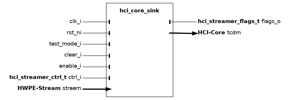
The hci_core_sink module is the high-level sink streamer performing a series of stores on a HCI-Core interface from an incoming HWPE-Stream data stream from a HWPE engine/datapath. The sink streamer is a composite module that makes use of many other fundamental IPs.
Fundamentally, a sink streamer acts as a specialized DMA engine acting out a predefined pattern from an hwpe_stream_addressgen_v4 to perform a burst of stores via a HCI-Core interface, consuming a HWPE-Stream data stream into the HCI-Core data field. The sink streamer is insensitive to memory latency. This is due to the nature of store streams, which are unidirectional (i.e. addr and data move in the same direction).
Misaligned accesses are supported by widening the HCI-Core data width by one memory-bank data width (BANK_DATA_WIDTH = ELEMENT_WIDTH * ELEMENTS_PER_BANK, 32 bits by default) compared to the HWPE-Stream that gets consumed by the streamer. The stream is shifted according to the address alignment and invalid bytes are disabled by unsetting their strb. This feature can be deactivated by unsetting the MISALIGNED_ACCESSES parameter; in this case, the sink will only work correctly if all data is aligned to a bank-word boundary.
Name |
Default |
Description |
TCDM_FIFO_DEPTH |
0 |
If >0, the module produces a HWPE-MemDecoupled interface and includes a TCDM FIFO of this depth. |
TRANS_CNT |
16 |
Number of bits supported in the transaction counter of the address generator, which will overflow at 2^ TRANS_CNT. |
MISALIGNED_ACCESSES |
1 |
If set to 0, the sink will not support non-bank-word-aligned HWPE-Mem accesses. |
ELEMENT_WIDTH |
8 |
Bit-width of a single data element; with ELEMENTS_PER_BANK it sets the bank data width. |
ELEMENTS_PER_BANK |
4 |
Number of elements stored in one memory bank; sets the bank data width. |
DIM_ENABLE_1H |
4’b0011 |
Bit-mask selecting how many address-generator dimensions are enabled (see hwpe_stream_addressgen_v4). |
Name |
Type |
Description |
req_start |
logic |
When 1, the sink streamer operation is started if it is ready. |
addressgen_ctrl |
ctrl_addressgen_v4_t |
Configuration of the address generator (see hwpe_stream_addressgen_v4). |
hci_core_sink_v2#
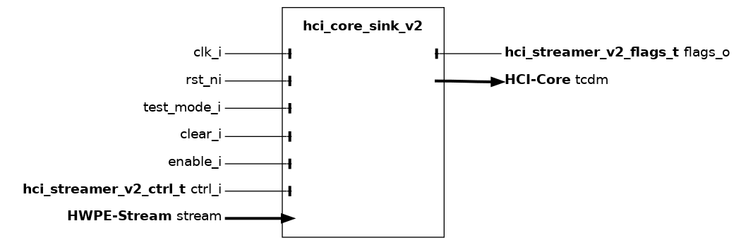
The hci_core_sink_v2 module is the high-level sink streamer performing a series of stores on a HCI-Core interface from an incoming HWPE-Stream data stream from a HWPE engine/datapath. The sink streamer is a composite module that makes use of many other fundamental IPs.
Fundamentally, a sink streamer acts as a specialized DMA engine acting out a predefined pattern from an hwpe_stream_addressgen_v3 to perform a burst of stores via a HCI-Core interface, consuming a HWPE-Stream data stream into the HCI-Core data field. The sink streamer is insensitive to memory latency. This is due to the nature of store streams, which are unidirectional (i.e. addr and data move in the same direction).
Misaligned accesses are supported by widening the HCI-Core data width of 32 bits compared to the HWPE-Stream that gets consumed by the streamer. The stream is shifted according to the address alignment and invalid bytes are disabled by unsetting their strb. This feature can be deactivated by unsetting the MISALIGNED_ACCESS parameter; in this case, the sink will only work correctly if all data is aligned to a word boundary.
Compared to the hci_core_sink module, the hci_core_sink_v2 introduce a job queue to enqueue streamer jobs earlier and streamline/optimize ctrl.
Name |
Default |
Description |
TCDM_FIFO_DEPTH |
2 |
If >0, the module produces a HWPE-MemDecoupled interface and includes a TCDM FIFO of this depth. |
TRANS_CNT |
16 |
Number of bits supported in the transaction counter of the address generator, which will overflow at 2^ TRANS_CNT. |
MISALIGNED_ACCESS |
1 |
If set to 0, the sink will not support non-word-aligned HWPE-Mem accesses. |
JOB_FIFO_DEPTH |
2 |
Depth of the streamer job queue. |
JOB_FIFO_PASSTHROUGH |
1 |
If set to 1 (default), the streamer job queue is passthrough, otherwise it’s a regular path-cutting FIFO. |
Name |
Type |
Description |
req_start |
logic |
When 1, the sink streamer operation is started if it is ready. |
addressgen_ctrl |
ctrl_addressgen_v3_t |
Configuration of the address generator (see hwpe_stream_addressgen_v3). |
Name |
Type |
Description |
ready_start |
logic |
1 when the sink streamer is ready to start operation, from the first IDLE state cycle on. |
done |
logic |
1 for one cycle when the streamer ends operation, in the cycle before it goes to IDLE state . |
addressgen_flags |
flags_addressgen_v3_t |
Address generator flags (see hwpe_stream_addresgen_v3). |
hwpe_stream_addressgen_v3 (deprecated for new HWPEs)#
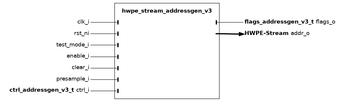
The hwpe_stream_addressgen_v3 module is used to generate addresses to load or store HWPE-Stream stream. In this version of the address generator, the address is itself carried within a HWPE-Stream, making it easily stallable. The address generator can be used to generate address from a three-dimensional space, which can be visited with configurable strides in all three dimensions.
The multiple loop functionality is partially overlapped by the functionality provided by the microcode processor hwce_ctrl_ucode that can be embedded in HWPEs. The latter is much more flexible and smaller, but less fast.
One iteration is performed per each cycle when enable_i is 1 and the output addr_o stream is ready. presample_i should be 1 in the first cycle in which the address generator can start generating addresses, and no further. The following piece of pseudo-C code resumes the basic functionality provided by the address generator.
hwpe_stream_addressgen_v3(
  int base_addr,                                          // base address (byte-aligned)
  int d0_len,    int d1_len,    int tot_len               // d0,d1,total length (in number of transactions)
  int d0_stride, int d1_stride, int d2_stride,            // d0,d1,d2 strides (in bytes)
  int *d0_addr,  int *d1_addr,  int *d2_addr,             // d0,d1,d2 addresses (by reference)
  int *d0_cnt,   int *d1_cnt,   int *ov_cnt               // d0,d1,overall counters (by reference)
) {
  // compute current address
  int current_addr = 0;
  int done = 0;
  if (dim_enable & 0x1 == 0) { // 1-dimensional streaming
    current_addr = base_addr + *d0_addr;
  }
  else if(dim_enable & 0x2 == 0) { // 2-dimensional streaming
    current_addr = base_addr + *d1_addr + *d0_addr;
  }
  else { // 3-dimensional streaming
    current_addr = base_addr + *d2_addr + *d1_addr + *d0_addr;
  }
  // update counters and dimensional addresses
  if(*ov_cnt == tot_len) {
    done = 1;
  }
  if((*d0_cnt < d0_len) || (dim_enable & 0x1 == 0)) {
    *d0_addr = *d0_addr + d0_stride;
    *d0_cnt  = *d0_cnt + 1;
  }
  else if ((*d1_cnt < d1_len) || (dim_enable & 0x2 == 0)) {
    *d0_addr = 0;
    *d1_addr = *d1_addr + d1_stride;
    *d0_cnt  = 1;
    *d1_cnt  = *d1_cnt + 1;
  }
  else if ((*d2_cnt < d2_len) || (dim_enable & 0x4 == 0)) {
    *d0_addr = 0;
    *d1_addr = 0;
    *d2_addr = *d2_addr + d2_stride;
    *d0_cnt  = 1;
    *d1_cnt  = 1;
    *d2_cnt  = *d2_cnt + 1;
  }
  else {
    *d0_addr = 0;
    *d1_addr = 0;
    *d2_addr = 0;
    *d3_addr = *d3_addr + d3_stride;
    *d0_cnt  = 1;
    *d1_cnt  = 1;
    *d2_cnt  = 1;
  }
  *ov_cnt = *ov_cnt + 1;
  return current_addr, done;
}
Name |
Default |
Description |
TRANS_CNT |
32 |
Number of bits supported in the transaction counter, which will overflow at 2^ TRANS_CNT. |
CNT |
32 |
Number of bits supported in non-transaction counters, which will overflow at 2^ CNT. |
Name |
Type |
Description |
done |
logic |
1 when the address generation has finished. |
hwpe_stream_addressgen_v4#
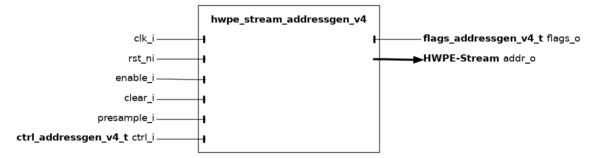
The hwpe_stream_addressgen_v4 module is used to generate addresses to load or store HWPE-Stream stream. In this version of the address generator, the address is itself carried within a HWPE-Stream, making it easily stallable. The address generator can be used to generate address from a four-dimensional space, which can be visited with configurable strides in all four dimensions.
The multiple loop functionality is partially overlapped by the functionality provided by the microcode processor hwce_ctrl_ucode that can be embedded in HWPEs. The latter is much more flexible and smaller, but less fast.
One iteration is performed per each cycle when enable_i is 1 and the output addr_o stream is ready. presample_i should be 1 in the first cycle in which the address generator can start generating addresses, and no further. The following piece of pseudo-C code resumes the basic functionality provided by the address generator.
hwpe_stream_addressgen_v4(
  int base_addr,                                                       // base address (byte-aligned)
  int d0_len,    int d1_len,    int d2_len,    int tot_len             // d0,d1,d2,total length (in number of transactions)
  int d0_stride, int d1_stride, int d2_stride, int d3_stride,          // d0,d1,d2,d3 strides (in bytes)
  int *d0_addr,  int *d1_addr,  int *d2_addr,  int *d3_addr,           // d0,d1,d2,d3 addresses (by reference)
  int *d0_cnt,   int *d1_cnt,   int *d2_cnt,   int *ov_cnt             // d0,d1,d2,overall counters (by reference)
) {
  // compute current address
  int current_addr = 0;
  int done = 0;
  if (dim_enable & 0x1 == 0) { // 1-dimensional streaming
    current_addr = base_addr + *d0_addr;
  }
  else if(dim_enable & 0x2 == 0) { // 2-dimensional streaming
    current_addr = base_addr + *d1_addr + *d0_addr;
  }
  else if(dim_enable & 0x4 == 0) { // 3-dimensional streaming
    current_addr = base_addr + *d2_addr + *d1_addr + *d0_addr;
  }
  else { // 4-dimensional streaming
    current_addr = base_addr + *d3_addr + *d2_addr + *d1_addr + *d0_addr;
  }
  // update counters and dimensional addresses
  if(*ov_cnt == tot_len) {
    done = 1;
  }
  if((*d0_cnt < d0_len) || (dim_enable & 0x1 == 0)) {
    *d0_addr = *d0_addr + d0_stride;
    *d0_cnt  = *d0_cnt + 1;
  }
  else if ((*d1_cnt < d1_len) || (dim_enable & 0x2 == 0)) {
    *d0_addr = 0;
    *d1_addr = *d1_addr + d1_stride;
    *d0_cnt  = 1;
    *d1_cnt  = *d1_cnt + 1;
  }
  else if ((*d2_cnt < d2_len) || (dim_enable & 0x4 == 0)) {
    *d0_addr = 0;
    *d1_addr = 0;
    *d2_addr = *d2_addr + d2_stride;
    *d0_cnt  = 1;
    *d1_cnt  = 1;
    *d2_cnt  = *d2_cnt + 1;
  }
  else if ((*d3_cnt < d3_len) || (dim_enable & 0x8 == 0)) {
    *d0_addr = 0;
    *d1_addr = 0;
    *d2_addr = 0;
    *d3_addr = *d3_addr + d3_stride;
    *d0_cnt  = 1;
    *d1_cnt  = 1;
    *d2_cnt  = 1;
    *d3_cnt  = *d3_cnt + 1;
  }
  else {
    *d0_addr = 0;
    *d1_addr = 0;
    *d2_addr = 0;
    *d3_addr = 0;
    *d4_addr = *d4_addr + d4_stride;
    *d0_cnt  = 1;
    *d1_cnt  = 1;
    *d2_cnt  = 1;
    *d3_cnt  = 1;
  }
  *ov_cnt = *ov_cnt + 1;
  return current_addr, done;
}
Name |
Default |
Description |
TRANS_CNT |
32 |
Number of bits supported in the transaction counter, which will overflow at 2^ TRANS_CNT. |
CNT |
32 |
Number of bits supported in non-transaction counters, which will overflow at 2^ CNT. |
Name |
Type |
Description |
base_addr |
logic[31:0] |
Byte-aligned base address of the stream in the HWPE-accessible memory. |
tot_len |
logic[31:0] |
Total number of transactions in stream; only the TRANS_CNT LSB are actually used. |
d0_len |
logic[31:0] |
d0 length in number of transactions |
d0_stride |
logic[31:0] |
d0 stride in bytes |
d1_len |
logic[31:0] |
d1 length in number of transactions |
d1_stride |
logic[31:0] |
d1 stride in bytes |
d2_len |
logic[31:0] |
d2 length in number of transactions |
d2_stride |
logic[31:0] |
d2 stride in bytes |
d3_len |
logic[31:0] |
d3 length in number of transactions |
d3_stride |
logic[31:0] |
d3 stride in bytes |
d4_stride |
logic[31:0] |
d4 stride in bytes |
dim_enable_1h |
logic[3:0] |
One-hot switch to enable 5-d counting (1111), 4-d (0111), 3-d (0011), 2-d (0001), or 1-d (0000). |
Name |
Type |
Description |
done |
logic |
1 when the address generation has finished. |
Plain HWPE-Mem Streamer modules (deprecated)#
The “plain” HWPE-Mem Streamer modules, although still functional, have generally been superseded by the HCI Streamer modules. We suggest using those for new designs.
Streamer modules constitute the heart of the IPs use to interface HWPEs with a PULP system. They include all the modules that are used to generate HWPE-Streams from address patterns on the TCDM, including the address generation itself, data realignment to enable access to data located at non-byte-aligned addresses, strobe generation to selectively disable parts of a stream, and the main streamer source and sink modules used to put these functions together. Modules performing these functions can be found within the rtl/streamer subfolder of the hwpe-stream repository.
Two main streamer modules (hwpe_stream_source and hwpe_stream_sink) are composite of several other IPs, including address generation and strobe generation blocks included in this section, as well as of basic HWPE-Stream management blocks.
hwpe_stream_source#
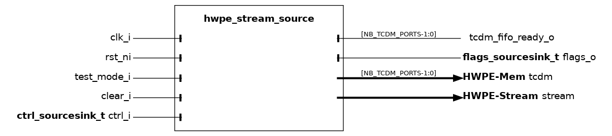
The hwpe_stream_source module is the high-level source streamer performing a series of loads on a HWPE-Mem or HWPE-MemDecoupled interface and producing a HWPE-Stream data stream to feed a HWPE engine/datapath. The source streamer is a composite module that makes use of many other fundamental IPs. Its architecture is shown in :numfig: _hwpe_stream_source_archi.
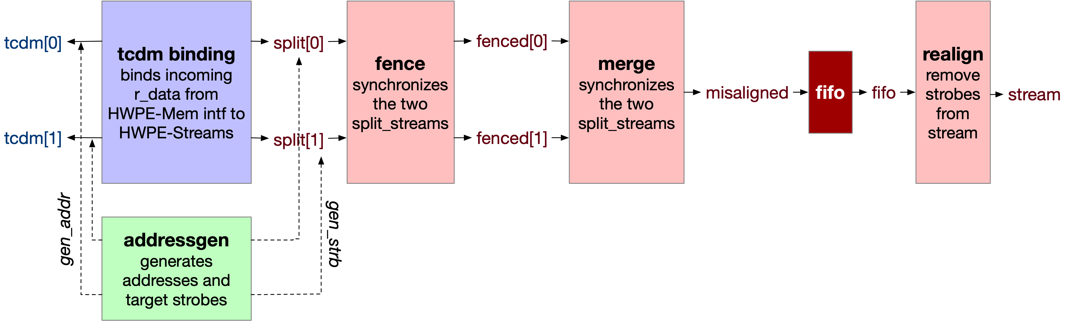
Fig. 9 Architecture of the source streamer.#
Fundamentally, a source streamer acts as a specialized DMA engine acting out a predefined pattern from an hwpe_stream_addressgen to perform a burst of loads via a HWPE-Mem interface, producing a HWPE-Stream data stream from the HWPE-Mem r_data field.
Depending on the DECOUPLED parameter, the streamer supports delayed accesses using a HWPE-MemDecoupled interface. The source streamer does not include any TCDM FIFO inside on its own; rather, it provides a specific tcdm_fifo_ready_o output signal that can be hooked to an external hwpe_stream_tcdm_fifo_load. tcdm_fifo_ready_o provides a backpressure mechanism from the source streamer to the TCDM FIFO (this is unnecessary in the case of TCDM FIFOs for store).
Name |
Default |
Description |
DECOUPLED |
0 |
If 1, the module expects a HWPE-MemDecoupled interface instead of HWPE-Mem. |
DATA_WIDTH |
32 |
Width of input/output streams (multiple of 32). |
LATCH_FIFO |
0 |
If 1, use latches instead of flip-flops (requires special constraints in synthesis). |
TRANS_CNT |
16 |
Number of bits supported in the transaction counter of the address generator, which will overflow at 2^ TRANS_CNT. |
REALIGNABLE |
1 |
If set to 0, the source will not support non-word-aligned HWPE-Mem accesses. |
Name |
Type |
Description |
req_start |
logic |
When 1, the source streamer operation is started if it is ready. |
addressgen_ctrl |
ctrl_addressgen_t |
Configuration of the address generator (see hwpe_stream_addresgen). |
Name |
Type |
Description |
ready_start |
logic |
1 when the source streamer is ready to start operation. |
done |
logic |
1 for one cycle when the streamer ends operation. |
addressgen_flags |
flags_addressgen_t |
Address generator flags (see hwpe_stream_addresgen). |
ready_fifo |
logic |
Unused. |
hwpe_stream_sink#
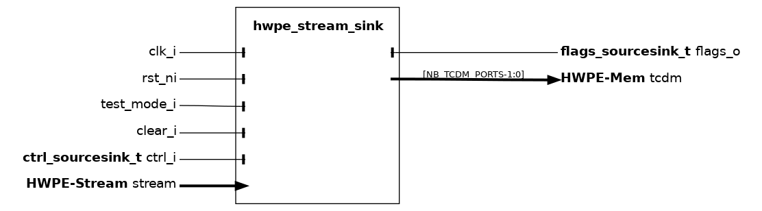
The hwpe_stream_sink module is the high-level sink streamer performing a series of stores on a HWPE-Mem or HWPE-MemDecoupled interface from an incoming HWPE-Stream data stream from a HWPE engine/datapath. The sink streamer is a composite module that makes use of many other fundamental IPs. Its architecture is shown in :numfig: _hwpe_stream_sink_archi.
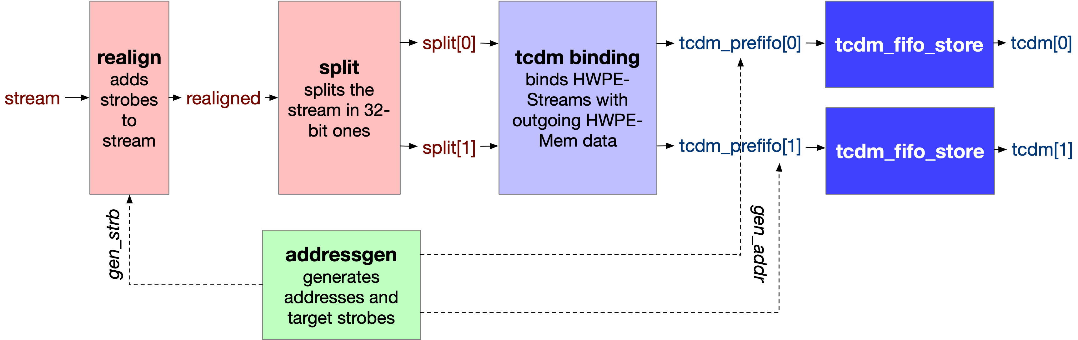
Fig. 10 Architecture of the source streamer.#
Fundamentally, a ink streamer acts as a specialized DMA engine acting out a predefined pattern from an hwpe_stream_addressgen to perform a burst of stores via a HWPE-Mem interface, consuming a HWPE-Stream data stream into the HWPE-Mem data field.
The sink streamer indifferently supports standard HWPE-Mem or delayed HWPE-MemDecoupled accesses. This is due to the nature of store streams, that are unidirectional (i.e. addr and data move in the same direction) and hence insensitive to latency.
Name |
Default |
Description |
TCDM_FIFO_DEPTH |
2 |
If >0, the module produces a HWPE-MemDecoupled interface and includes a TCDM FIFO of this depth. |
DATA_WIDTH |
32 |
Width of input/output streams. |
LATCH_FIFO |
0 |
If 1, use latches instead of flip-flops (requires special constraints in synthesis). |
TRANS_CNT |
16 |
Number of bits supported in the transaction counter of the address generator, which will overflow at 2^ TRANS_CNT. |
REALIGNABLE |
1 |
If set to 0, the sink will not support non-word-aligned HWPE-Mem accesses. |
Name |
Type |
Description |
req_start |
logic |
When 1, the sink streamer operation is started if it is ready. |
addressgen_ctrl |
ctrl_addressgen_t |
Configuration of the address generator (see hwpe_stream_addresgen). |
Name |
Type |
Description |
ready_start |
logic |
1 when the sink streamer is ready to start operation. |
done |
logic |
1 for one cycle when the streamer ends operation. |
addressgen_flags |
flags_addressgen_t |
Address generator flags (see hwpe_stream_addresgen). |
ready_fifo |
logic |
Unused. |
hwpe_stream_addressgen#
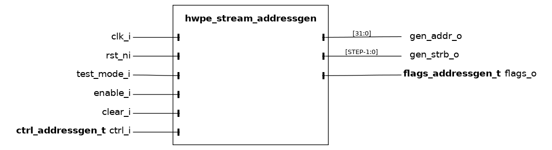
_**hwpe_stream_addressgen** is DEPRECATED. New designs should use hwpe_stream_addressgen_v3 instead._
The hwpe_stream_addressgen module is used to generate addresses to load or store HWPE-Stream streams, as well as the related byte enable strobes (gen_addr_o and gen_strb_o respectively). The address generator can be used to generate address from a three-dimensional space of “words”, “lines” and “features”. Lines and features can be separated by a certain stride, and a roll parameter can be used to reuse the same offsets multiple times.
The multiple loop functionality is partially overlapped by the functionality provided by the microcode processor hwce_ctrl_ucode that can be embedded in HWPEs. The latter is much more flexible and smaller, but less fast. When using a single loop in the address generator, the HWPE designer should statically set line_stride =0, feat_length =1, feat_stride =0.
The address generation loop considers three-dimensional vectors, where the three dimensions are called packet, line and features from the innermost to the outermost. One iteration is performed per each cycle when enable_i is 1. Feature loops can behave in two different fashions, modeled after the behavior of input/output features in CNNs. The following piece of code resumes the basic functionality provided by the address generator, discarding more complex situations where the address is misaligned (resulting in one more transaction, introduced automatically).
int word_addr=0, line_addr=0, feat_addr=0;
int trans_idx=0;
while(trans_idx < trans_size) {
  if(!enable)
    continue;
  for(int feat_idx=0; feat_idx<feat_roll; feat_idx++) { // feature loop
    for(int line_idx=0; line_idx<feat_length; line_idx++) { // line loop
      for(int word_idx=0; word_idx<line_length; word_idx++) { // word loop
        gen_addr = base_addr + feat_addr + line_addr + word_idx * STEP;
      }
      line_addr += line_stride;
    }
    if((loop_outer) && (feat_idx == feat_roll-1)) {
      feat_addr += feat_stride;
      feat_idx  = 0;
    }
    else if ((!loop_outer) && (feat_idx < feat_roll-1)){
      feat_addr += feat_stride;
    }
    else if ((!loop_outer) && (feat_idx == feat_roll-1)){
      feat_addr = 0;
      feat_idx  = 0;
    }
  }
}
Name |
Default |
Description |
REALIGN_TYPE |
HWPE_STREAM_REALIGN_SOURCE |
Type of realignment, can be set to HWPE_STREAM_REALIGN{SOURCE,SINK}. |
STEP |
4 |
Step of address generation (untested with != 4). |
TRANS_CNT |
16 |
Number of bits supported in the transaction counter, which will overflow at 2^ TRANS_CNT. |
CNT |
10 |
Number of bits supported in non-transaction counters, which will overflow at 2^ CNT. |
DELAY_FLAGS |
0 |
If 1, delay the production of flags by one cycle. |
Name |
Type |
Description |
base_addr |
logic[31:0] |
Byte-aligned base address of the stream in the HWPE-accessible memory. |
trans_size |
logic[31:0] |
Total size of transaction; only the TRANS_CNT LSB are actually used. |
line_stride |
logic[15:0] |
Distance between two adjacent lines in bytes. |
line_length |
logic[15:0] |
Length of a line in words, rounded by including also incomplete final words. |
feat_stride |
logic[15:0] |
Distance between two adjacent features in bytes. |
feat_length |
logic[15:0] |
Length of a feature in number of lines. |
loop_outer |
logic |
Whether this corresponds to an outer or inner feature loop. |
feat_roll |
logic[15:0] |
After this number of features, depending on loop_outer, feature index will be rolled back or incremented. |
realign_type |
logic |
Unused. |
line_length_remainder |
logic[7:0] |
Unused. |
Name |
Type |
Description |
realign_flags |
ctrl_realign_t |
Control signals to be used for realignment by hwpe_stream_{source,sink}_realign modules. |
word_update |
logic |
1 when the word loop has been updated. |
line_update |
logic |
1 when the line loop has been updated. |
feat_update |
logic |
1 when the feature loop has been updated. |
in_progress |
logic |
1 when the address generation has progressed. |
hwpe_stream_strbgen#
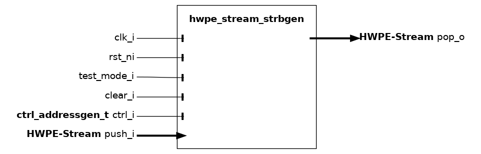
The hwpe_stream_strbgen module is used to generate strobes for load or store HWPE-Stream streams, in case of incomplete transfers. It uses information passed through the same configuration struct used for the address generator.
Name |
Default |
Description |
DATA_WIDTH |
32 |
Width of input/output streams. |
Name |
Type |
Description |
base_addr |
logic[31:0] |
Unused. |
trans_size |
logic[31:0] |
Unused. |
line_stride |
logic[15:0] |
Unused. |
line_length |
logic[15:0] |
Length of a line in words, rounded by including also incomplete final words. |
feat_stride |
logic[15:0] |
Unused. |
feat_length |
logic[15:0] |
Unused. |
loop_outer |
logic |
Unused. |
feat_roll |
logic[15:0] |
Unused. |
realign_type |
logic |
Unused. |
line_length_remainder |
logic[7:0] |
Number of valid bytes in the final word in a line; if 0, the final word is considered fully valid. |
hwpe_stream_sink_realign#
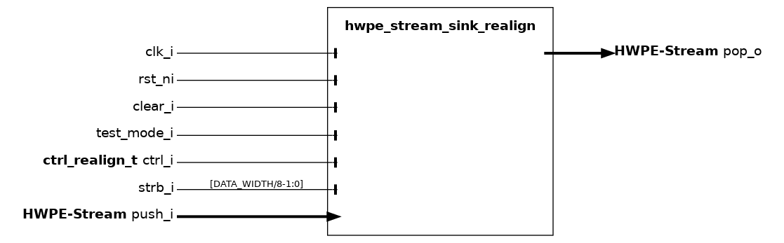
The hwpe_stream_sink_realign module realigns HWPE-Streams to prepare them for storage in memory. Specifically, it rotates strb signals according to its control interface, produced along with addresses in the address generator.
Name |
Default |
Description |
DATA_WIDTH |
32 |
Width of input/output streams. |
Name |
Type |
Description |
enable |
logic |
Unused. |
strb_valid |
logic |
Unused. |
realign |
logic |
If 1, the realigner is actively used to generate strobed HWPE-Streams. If 0, it is bypassed. |
first |
logic |
Strobe at 1 for the first packet in a line. |
last |
logic |
Strobe at 1 for the last packet in a line. |
last_packet |
logic |
Strobe at 1 for the last packet of the transfer. |
line_length |
logic[15:0] |
Unused. |
hwpe_stream_source_realign#
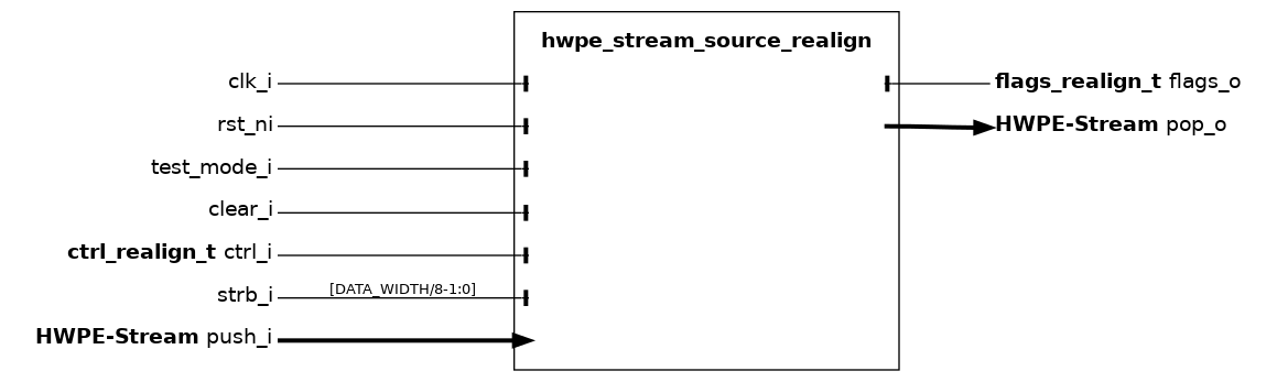
The hwpe_stream_source_realign module realigns HWPE-Streams loaded in a misaligned fashion from memory. Specifically, it rotates strb signals according to its control interface, produced along with addresses in the address generator.
Name |
Default |
Description |
DECOUPLED |
0 |
If 1, the module expects a HWPE-MemDecoupled interface instead of HWPE-Mem. |
DATA_WIDTH |
32 |
Width of input/output streams. |
STRB_FIFO_DEPTH |
4 |
Depth of the FIFO queue used for strobes; when full, the realigner will lower its ready signal at the input interface. |
Name |
Type |
Description |
enable |
logic |
If 0, the realigner is fully clock-gated. |
strb_valid |
logic |
If 1, the strobe at the strb_i interface is considered valid. |
realign |
logic |
If 1, the realigner is actively used to generate strobed HWPE-Streams. If 0, it is bypassed. |
first |
logic |
Strobe at 1 for the first packet in a line. |
last |
logic |
Strobe at 1 for the last packet in a line. |
last_packet |
logic |
Strobe at 1 for the last packet of the transfer. |
line_length |
logic[15:0] |
Length of a line in words, rounded by including also incomplete final words. |
Name |
Type |
Description |
decoupled_stall |
logic |
Do not use. |
HCI Interconnect modules#
The HCI Interconnect modules implement the routers, arbiters, and interconnects used to connect one or more HWPEs to the shared memory of a PULP cluster. The top-level hci_interconnect module composes a logarithmic interconnect and a router into a complete HCI interconnect; the other modules are the building blocks used internally or exposed for advanced use cases. Modules performing these functions can be found within the rtl/interco subfolder (and at the top level) of the hci repository.
hci_interconnect#
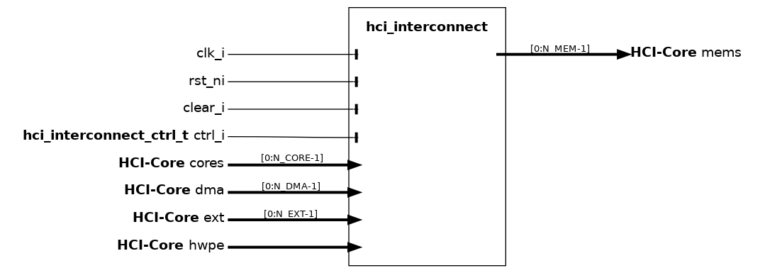
Convenience top-level for the PULP heterogeneous cluster interconnect. It wraps both a logarithmic interconnect (LIC) and an (optional) HCI router meant to realize a LIC and a HWPE branch of the interconnect, respectively. The two branches are (optionally) arbitrated via a HCI arbiter.
Name |
Default |
Description |
N_HWPE |
1 |
Number of HWPEs attached as initiator to the interconnect (LIC or HWPE branch). |
N_CORE |
8 |
Number of cores attached as initiator to the interconnect (LIC branch). |
N_DMA |
4 |
Number of DMA ports attached as initiator to the interconnect (LIC branch). |
N_EXT |
4 |
Number of external ports attached as initiator to the interconnect (LIC branch). |
N_MEM |
16 |
Number of memory banks attached as target to the interconnect. |
TS_BIT |
21 |
Bit passed to LIC to define test&set aliased memory region. |
IW |
N_HWPE+N_CORE+N_DMA+N_EXT |
ID Width. |
EXPFIFO |
0 |
Depth of HCI router FIFO. |
SEL_LIC |
0 |
Kind of LIC to instantiate (0=regular L1, 1=L2). |
hci_router#
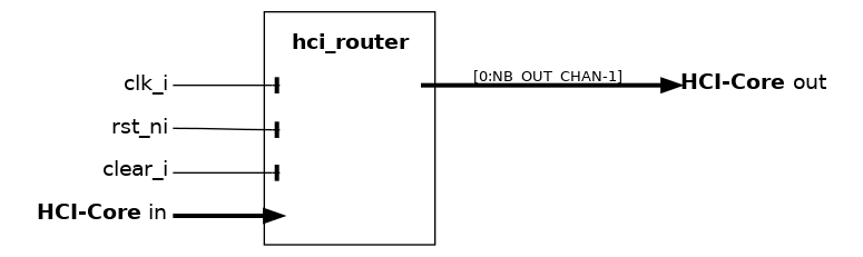
The hci_router is a specialized router used to build interconnects in a heterogeneous PULP cluster. It takes as input a single in HCI channel of width DWH (typically “wide”, i.e., greater than one bank word) that gets routed without arbitration to DWH/BANK_WORD_WIDTH adjacent out targets from a set of NB_OUT_CHAN out channels (typically, one per memory bank). Routing is performed by splitting the address of the DWH-bit wide word in an index and an offset part; the lowest $clog2(BANK_WORD_WIDTH/BANK_ELEM_WIDTH) address bits are the element offset within a bank word and are ignored. The index is used to select which out targets need to propagate the request, while the offset is used to compute the target-level address for each out channel – since word interleaving is assumed, the same address is generally propagated to all targeted out channels. However, if index > NB_OUT_CHAN-DWH/BANK_WORD_WIDTH, then the set of selected targets “wraps around”: the first channels are activated, propagating the offset incremented by one bank word. See https://ieeexplore.ieee.org/document/9903915 Sec. II-A (open-access) for details (the router is called a shallow router).
Name |
Default |
Description |
FIFO_DEPTH |
0 |
If > 0, insert a HCI FIFO of this depth after the input channel. |
NB_OUT_CHAN |
8 |
Number of output HCI channels (one per memory bank). |
BANK_WORD_WIDTH |
32 |
Bit-width of one output bank word. |
BANK_ELEM_WIDTH |
8 |
Bit-width of one element within a bank word (be granularity). |
USE_ECC |
0 |
If set to 1, enables ECC check bits propagation. |
FILTER_WRITE_R_VALID |
0 |
If 1, suppress r_valid responses generated by write transactions. |
hci_router_reorder#
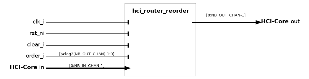
The hci_router_reorder module is the actual routing engine wrapped by hci_router (see hci_router). It accepts up to NB_IN_CHAN BANK_WORD_WIDTH-bit in HCI-Core channels and distributes their requests across NB_OUT_CHAN out channels (typically one per memory bank) according to the external order_i index, with no arbitration: per cycle, each in channel is routed to a distinct out channel determined by (order_i + i) mod NB_OUT_CHAN.
Because the wide-word access pattern enforced by hci_router is conflict-free by construction, the gnt of all in channels is the AND of all out grants - i.e., a transaction either fully proceeds or fully stalls. Read responses are returned with a fixed latency of one cycle and are demultiplexed back to the originating in channel via instances of addr_dec_resp_mux (one per in channel).
When USE_ECC is set, the $clog2(BANK_WORD_WIDTH)+2 Hsiao SEC-DED check bits of the ecc side-channel are routed alongside the data; otherwise they are tied off.
Name |
Default |
Description |
NB_IN_CHAN |
2 |
Number of input HCI-Core channels (typically DWH/BANK_WORD_WIDTH). |
NB_OUT_CHAN |
2 |
Number of output HCI-Core channels (one per memory bank). |
BANK_WORD_WIDTH |
32 |
Bit-width of one bank word (data width of each in/out channel). |
BANK_ELEM_WIDTH |
8 |
Bit-width of one element within a bank word (be strobe granularity). |
FILTER_WRITE_R_VALID |
0 |
If 1, suppress the r_valid pulse for write transactions on the response. |
USE_ECC |
0 |
If 1, propagate the ECC check bits alongside data. |
hci_arbiter#
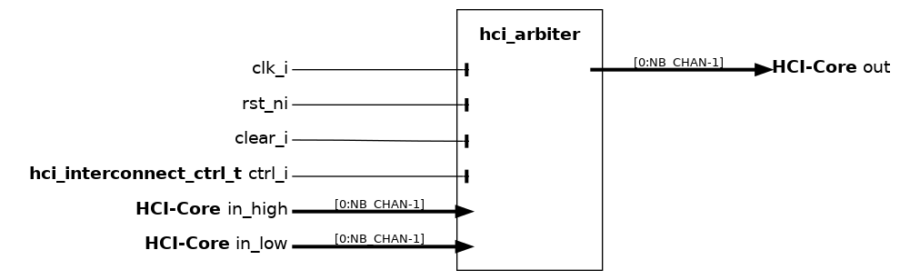
The hci_arbiter is a specialized arbiter used to build interconnects in a heterogeneous PULP cluster, and in particular to arbitrate between two sets of NB_CHAN input channels, one with “default high” (in_high) and the other with “default low” priority (in_low). The arbitration is meant to be performed generally at the direct boundary between the interconnect and the tightly-coupled memory banks. The arbiter uses a starvation-free unbalanced-priority scheme where one of the input channels has by default access to most of the bandwidth guaranteed by the output channels. To prevent starvation effects, depending on the control settings, the other input channel is always granted after a given number of stall cycles. For more details, see:
https://ieeexplore.ieee.org/document/9903915, Sec. II-A (open-access);
https://ieeexplore.ieee.org/document/10247945 , Sec. II-A, III-B, and III-C.
Name |
Default |
Description |
NB_CHAN |
2 |
Number of HCI channels. |
Name |
Type |
Description |
invert_prio |
logic |
When 1, invert priorities between in_high and in_low. |
priority_cnt_numerator |
logic[7:0] |
Maximum number of consecutive stalls on low-priority channel. |
priority_cnt_denominator |
logic[7:0] |
Clear condition of priority counter (max low-prio stalls + high-prio stalls). |
hci_arbiter_tree#
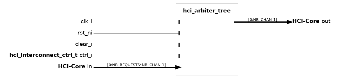
The hci_arbiter_tree is an arbitration tree designed using hci_arbiter as the submodule. The hci_arbiter_tree is designed as a binary tree
Name |
Default |
Description |
NB_REQUESTS |
1 |
Number of request ports |
NB_CHAN |
16 |
Number of ports per request |
hci_log_interconnect#
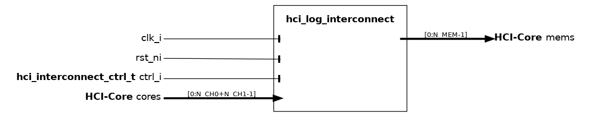
The hci_log_interconnect module wraps the standard PULP TCDM logarithmic interconnect (tcdm_interconnect configured with the LIC topology) and exposes its initiator and target ports as hci_core_intf instances. It is typically used as the LIC branch of the top-level hci_interconnect (see hci_interconnect), routing requests from N_CH0+N_CH1 initiator channels (cores, DMA, external masters) to N_MEM memory banks with full crossbar arbitration and starvation-free round-robin selection.
The wrapper takes care of “unrolling” the HCI-Core interface arrays into the flat signal arrays consumed by the underlying tcdm_interconnect, propagating data, user and ecc payloads transparently when the corresponding widths are non-zero.
Name |
Default |
Description |
N_CH0 |
16 |
Number of “channel 0” initiator ports (typically cores). |
N_CH1 |
4 |
Number of “channel 1” initiator ports (typically DMA / external). |
N_MEM |
32 |
Number of memory bank target ports. |
AWC |
DEFAULT_AW |
Address width on the initiator (core) side. |
AWM |
DEFAULT_AW |
Address width on the target (memory) side. |
DW |
DEFAULT_DW |
Data width. |
BW |
DEFAULT_BW |
Byte width (granularity of the byte enable). |
TS_BIT |
21 |
Bit position used to alias the test-and-set memory region. |
IW |
N_CH0+N_CH1 |
ID width (currently unused inside the interconnect). |
UW |
DEFAULT_UW |
Width of the side-channel user field. |
EW |
DEFAULT_EW |
Width of the side-channel ecc field. |
hci_new_log_interconnect#
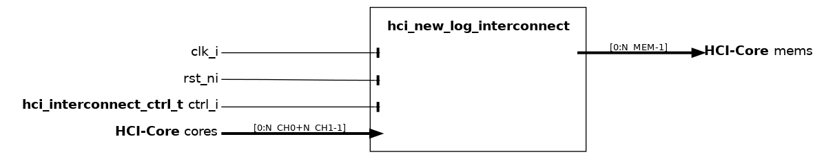
The hci_new_log_interconnect module is an alternative wrapper of the PULP TCDM logarithmic interconnect, based on the legacy new_XBAR_TCDM crossbar (as opposed to the tcdm_interconnect used by hci_log_interconnect). It exposes the same hci_core_intf-based initiator/target interface as hci_log_interconnect and carries native support for HCI-style test-and-set transactions via the data_ts_set_o side band of the underlying crossbar.
It is provided primarily for backward compatibility with platforms that already integrate new_XBAR_TCDM; for new designs, hci_log_interconnect is preferred.
Name |
Default |
Description |
N_CH0 |
16 |
Number of “channel 0” initiator ports (typically cores). |
N_CH1 |
4 |
Number of “channel 1” initiator ports (typically DMA / external). |
N_MEM |
32 |
Number of memory bank target ports. |
AWC |
DEFAULT_AW |
Address width on the initiator (core) side. |
AWM |
DEFAULT_AW |
Address width on the target (memory) side. |
DW |
DEFAULT_DW |
Data width. |
BW |
DEFAULT_BW |
Byte width (granularity of the byte enable). |
TS_BIT |
21 |
Bit position used to alias the test-and-set memory region. |
IW |
N_CH0+N_CH1 |
ID width propagated by the crossbar with the response. |
UW |
DEFAULT_UW |
Width of the side-channel user field. |
EW |
DEFAULT_EW |
Width of the side-channel ecc field. |
Safe HCI (ECC and parity)#
The Safe HCI modules provide end-to-end protection of HCI transactions for deployments with safety or reliability requirements. They are split in two complementary groups:
ECC modules implement the Error-Correcting Code side channel described in Optional ECC side channel. They provide encoders and decoders that protect data payloads and handshake signals, ECC-aware variants of the source, sink and interconnect modules, and a dedicated ECC manager that collects error reports and exposes them through a memory-mapped register file. These modules can be found within the rtl/ecc subfolder of the hci repository.
Parity (lockstep copy) modules implement a duplicated-path protection scheme in which a redundant copy source/sink runs in lockstep with the primary streamer and raises a fault when the two diverge. These modules can be found within the rtl/parity subfolder of the hci repository.
hci_ecc_enc#
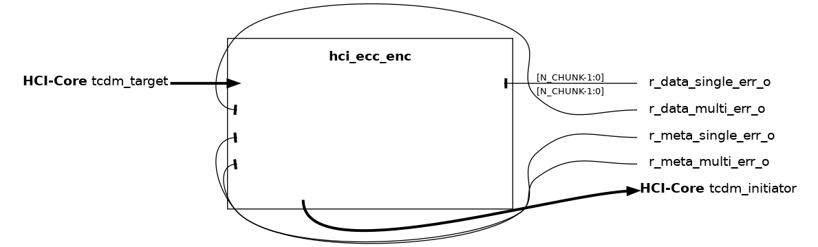
The hci_ecc_enc module handles ECC encoding and decoding of the HCI-Core interface payloads. It encodes the request phase payload, applying ECC protection to both data and metadata (add, wen, be, and optionally user fields). It decodes the response phase payload, recovering r_data and r_user fields from the ECC-protected response.
The request phase encoding covers: - If ENABLE_DATA is set, ECC protection is applied to the data field, split into multiple chunks. - Always applies ECC protection to the request metadata.
The response phase decoding covers: - ECC correction on the r_data field, chunked in the same manner as data. - ECC correction on the r_user field, if used.
The ECC encoding scheme follows a Hsiao code, providing single error correction and double error detection (SEC-DED). See pulp-platform/redundancy_cells). Errors are separately flagged for data and metadata, distinguishing single-bit and multi-bit corrections.
This module is the complementary counterpart to hci_ecc_dec, which instead applies ECC decoding during request and encoding during response.
data_ecc [EW-1 : EW_RQMETA] |
meta_ecc [EW_RQMETA-1 : 0] |
Zero padding [EW-1 : EW_RQMETA+EW_DW*N_CHUNK] |
r_data_ecc [EW_RQMETA+EW_DW*N_CHUNK-1 : EW_RQMETA] |
r_meta_ecc [EW_RQMETA-1 : 0] |
Name |
Default |
Description |
CHUNK_SIZE |
32 |
Width in bits of each chunk of data to protect individually. |
ENABLE_DATA |
1 |
If set to 1, performs data field’s encoding as well as metadata. |
hci_ecc_dec#
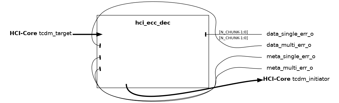
The hci_ecc_dec module handles ECC decoding and encoding of the HCI-Core interface payloads. It decodes the request phase payload, recovering both data and metadata (add, wen, be, and optionally user fields) from the the ECC-protected request. It encodes the response phase payload, adding ECC protection to the r_data and r_user fields.
The request phase decoding covers: - If ENABLE_DATA is set, ECC correction on the data field split into multiple chunks. - Always performs ECC correction on the request metadata.
The response phase encoding covers: - ECC generation for the r_data field, chunked in the same manner as data. - ECC generation for the r_user field, if used.
The ECC encoding scheme follows a Hsiao code, providing single error correction and double error detection (SEC-DED). See pulp-platform/redundancy_cells). Errors are separately flagged for data and metadata, distinguishing single-bit and multi-bit corrections.
This module is the complementary counterpart to hci_ecc_enc, which instead applies ECC encoding during request and decoding during response.
data_ecc [EW-1 : EW_RQMETA] |
meta_ecc [EW_RQMETA-1 : 0] |
Zero padding [EW-1 : EW_RQMETA+EW_DW*N_CHUNK] |
r_data_ecc [EW_RQMETA+EW_DW*N_CHUNK-1 : EW_RQMETA] |
r_meta_ecc [EW_RQMETA-1 : 0] |
Name |
Default |
Description |
CHUNK_SIZE |
32 |
Width in bits of each chunk of data to protect individually. |
ENABLE_DATA |
1 |
If set to 1, performs data field’s decoding as well as metadata. |
hci_ecc_source#
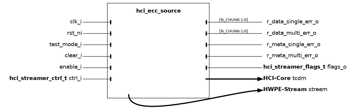
The hci_ecc_source module acts as an ECC-extended wrapper around the hci_core_source module. It extends the functionality with ECC support, while preserving its original behavior; please refer to hci_core_source for detailed functional information on the underlying streamer.
Internally, the module instantiates a hci_core_source driving an unprotected “virtual” HCI-Core interface, and a hci_ecc_enc block that applies ECC encoding/decoding to bridge the virtual interface to the actual ECC-protected tcdm initiator port. ECC error flags are exposed on dedicated outputs for collection by a hci_ecc_manager.
Compared to the underlying hci_core_source, this module exposes the additional CHUNK_SIZE parameter, which controls the granularity of ECC protection on the data field (see hci_ecc_enc).
Name |
Default |
Description |
LATCH_FIFO |
0 |
If 1, use latches instead of flip-flops (requires special constraints in synthesis). |
TRANS_CNT |
16 |
Number of bits supported in the transaction counter of the address generator, which will overflow at 2^ TRANS_CNT. |
ADDR_MIS_DEPTH |
8 |
Depth of the misaligned address FIFO. This must be equal to the max-latency between the HCI-Core gnt and r_valid. |
MISALIGNED_ACCESSES |
1 |
If set to 0, the source will not support non-word-aligned HCI-Core accesses. |
PASSTHROUGH_FIFO |
0 |
If set to 1, the address FIFO will be capable of fall-through operation (i.e., skipping the FIFO latency entirely). |
RESP_FIFO_DEPTH |
0 |
If > 0, responses are buffered through a HWPE-Stream FIFO of this depth before reaching the output stream. |
CHUNK_SIZE |
32 |
Width in bits of each chunk of data to protect individually with ECC. |
Name |
Type |
Description |
r_data_single_err_o |
logic[N_CHUNK-1:0] |
One bit per data chunk, asserted when a single-bit (correctable) error is found. |
r_data_multi_err_o |
logic[N_CHUNK-1:0] |
One bit per data chunk, asserted when a multi-bit (uncorrectable) error is found. |
r_meta_single_err_o |
logic |
Asserted when a single-bit (correctable) error is found in response metadata. |
r_meta_multi_err_o |
logic |
Asserted when a multi-bit (uncorrectable) error is found in response metadata. |
hci_ecc_sink#

The hci_ecc_sink module acts as an ECC-extended wrapper around the hci_core_sink module. It extends the functionality with ECC support, while preserving its original behavior; please refer to hci_core_sink for detailed functional information on the underlying streamer.
Internally, the module instantiates a hci_core_sink driving an unprotected “virtual” HCI-Core interface, and a hci_ecc_enc block that applies ECC encoding to bridge the virtual interface to the actual ECC-protected tcdm initiator port. Since the sink only performs stores, no response-phase error flags are exposed; the encoder output ports for read-back checks are left unconnected.
Name |
Default |
Description |
TCDM_FIFO_DEPTH |
0 |
If >0, the module produces a HWPE-MemDecoupled interface and includes a TCDM FIFO of this depth. |
TRANS_CNT |
16 |
Number of bits supported in the transaction counter of the address generator, which will overflow at 2^ TRANS_CNT. |
MISALIGNED_ACCESSES |
1 |
If set to 0, the sink will not support non-word-aligned HCI-Core accesses. |
hci_ecc_interconnect#
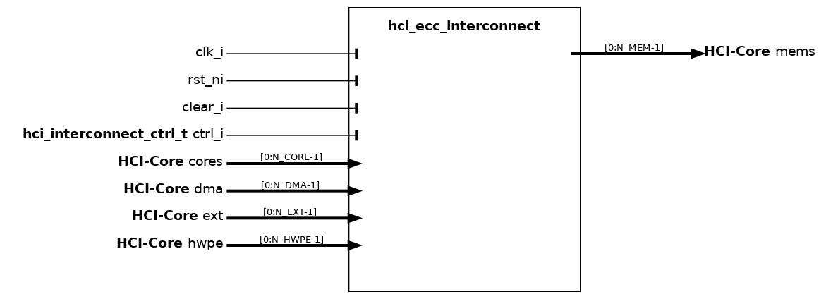
The hci_ecc_interconnect module is the ECC-protected variant of hci_interconnect (see hci_interconnect): it wraps both a logarithmic interconnect (LIC) and an (optional) HCI router to realize the LIC and HWPE branches of a cluster interconnect, optionally arbitrated by an HCI arbiter, and additionally instantiates ECC encoders/decoders on each initiator port and an hci_ecc_manager register file to expose error counters to software.
Refer to hci_interconnect for the description of the underlying arbitration and routing scheme, and to hci_ecc_enc / hci_ecc_dec for the details of the ECC protection layout.
Name |
Default |
Description |
N_HWPE |
1 |
Number of HWPEs attached as initiator to the interconnect (LIC or HWPE branch). |
N_CORE |
8 |
Number of cores attached as initiator to the interconnect (LIC branch). |
N_DMA |
4 |
Number of DMA ports attached as initiator to the interconnect (LIC branch). |
N_EXT |
4 |
Number of external ports attached as initiator to the interconnect (LIC branch). |
N_MEM |
16 |
Number of memory banks attached as target to the interconnect. |
TS_BIT |
21 |
Bit passed to LIC to define test&set aliased memory region. |
IW |
N_HWPE+N_CORE+N_DMA+N_EXT |
ID Width. |
EXPFIFO |
0 |
Depth of HCI router FIFO. |
SEL_LIC |
0 |
Kind of LIC to instantiate (0=regular L1, 1=L2). |
CHUNK_SIZE |
32 |
Width in bits of each chunk of data to protect individually. |
hci_ecc_manager#
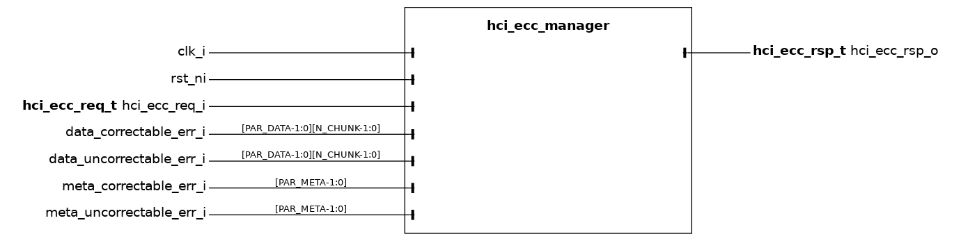
The hci_ecc_manager module logs faults on data and metadata fields, distinguishing correctable and uncorrectable errors, as detected along the hci_ecc_interconnect, and collects them into software-accessible registers.
Per-chunk and per-source error flags from the ECC-protected interconnect are reduced through population counters and accumulated into four 32-bit saturation-free counters, exposed via a reg_iface device port through the auto-generated hci_ecc_manager_reg_top register file. Software can read each counter at any time and clear it by writing zero (rw0c access).
Name |
Default |
Description |
N_CHUNK |
1 |
Number of chunks in which the wide data channel is split for independent ECC processing. |
PAR_DATA |
1 |
Number of independent parallel data error sources monitored across the interconnect. |
PAR_META |
1 |
Number of independent parallel metadata error sources monitored across the interconnect. |
Name |
Offset**| **Description |
|
data_correctable_errors |
0x00 |
Running count of single-bit (correctable) errors on the data payload. |
data_uncorrectable_errors |
0x04 |
Running count of multi-bit (uncorrectable) errors on the data payload. |
metadata_correctable_errors |
0x08 |
Running count of single-bit (correctable) errors on the request metadata. |
metadata_uncorrectable_errors |
0x0C |
Running count of multi-bit (uncorrectable) errors on the request metadata. |
hci_ecc_manager_reg_top#

The hci_ecc_manager_reg_top module is the auto-generated register file top wrapper used by hci_ecc_manager to expose its error counters on a reg_iface device port. It is produced by the lowRISC reggen tool from the hci_ecc_manager.hjson description and contains the address decoder, write-enable logic and the registered state for the four error counters (see hci_ecc_manager).
Name |
Default |
Description |
reg_req_t |
logic |
Type of the inbound reg_iface request struct. |
reg_rsp_t |
logic |
Type of the outbound reg_iface response struct. |
AW |
4 |
Address width of the register block (in bits). |
The module is not meant to be instantiated directly by end users; it is exclusively used as a sub-block of hci_ecc_manager and is regenerated from the hjson description by the reggen flow when the register layout changes.
hci_copy_source#

The hci_copy_source module opens a duplicated (lockstep-copy) path on an HCI-Core interface. It monitors a primary HCI-Core stream on the tcdm_main port (as a passive monitor modport) and reproduces it on a redundant tcdm_copy initiator port; the redundant stream is then meant to run in lockstep through a parallel chain of HCI modules and be closed by a matching hci_copy_sink (see hci_copy_sink) that compares the two streams and raises a fault on divergence.
The granularity of duplication is controlled by the COPY_TYPE and COMPARE_TYPE parameters, which configure respectively the main-to-copy driving and the copy-to-main checking. The selected mode must match on both ends of the duplicated path.
Name |
Default |
Description |
COPY_TYPE |
COPY |
Depth of main-to-copy duplication (see hci_copy_t below). |
COMPARE_TYPE |
COPY |
Depth of copy-to-main comparison. |
DONT_CARE |
1 |
Constant value driven on signals that are not propagated by the current mode. |
The supported hci_copy_t modes (shared with hci_copy_sink) are:
COPY: Fully copy and compare every HCI signal.
NO_ECC: Copy and compare everything except the ecc side-channel.
NO_DATA: Copy and compare everything except the data payload.
CTRL_ONLY: No copy or compare of data or ecc signals; only the control plane is duplicated.
hci_copy_sink#
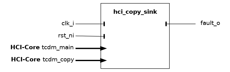
The hci_copy_sink module closes a duplicated (lockstep-copy) path on an HCI-Core interface. It is meant to be paired with a hci_copy_source (see hci_copy_source) placed at the head of a chain of HCI modules: the tcdm_main port monitors the primary HCI-Core stream (as a passive monitor modport), while the tcdm_copy port consumes the redundant stream produced by the matching hci_copy_source. Each cycle the sink compares the two streams field-by-field and raises fault_o whenever they diverge, providing single-fault detection on the protected segment.
The granularity of the comparison is controlled by the COPY_TYPE and COMPARE_TYPE parameters, which configure respectively the main-to-copy driving and the copy-to-main checking. The selected mode must match on both ends of the duplicated path.
Name |
Default |
Description |
COPY_TYPE |
COPY |
Depth of main-to-copy duplication (see hci_copy_t below). |
COMPARE_TYPE |
COPY |
Depth of copy-to-main comparison. |
DONT_CARE |
1 |
Constant value driven on signals that are not propagated by the current mode. |
The supported hci_copy_t modes (shared with hci_copy_source) are:
COPY: Fully copy and compare every HCI signal.
NO_ECC: Copy and compare everything except the ecc side-channel.
NO_DATA: Copy and compare everything except the data payload.
CTRL_ONLY: No copy or compare of data or ecc signals; only the control plane is duplicated.
Control interface modules (HWPE-Periph)#
The control interface of HWPEs exposes a HWPE-Periph interface that is used to program a memory-mapped register file. Several IPs can be used to compose the control interface, delivering a standard accelerator control interface that is described below. Modules performing these functions can be found within the rtl/ subfolder of the hwpe-ctrl repository.
hwpe_ctrl_target#
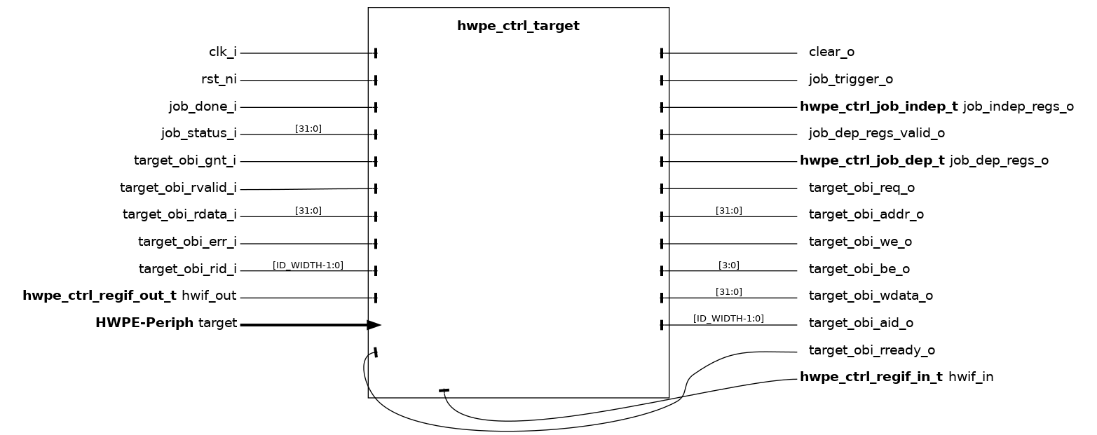
The hwpe_ctrl_target module implements the control-side target (slave) port of an HWPE, exposing a hwpe_ctrl_intf_periph interface used by an external core to program a memory-mapped register file. It supersedes the deprecated hwpe_ctrl_slave module: rather than hard-coding a register file, it relies on a register interface that is generated out of a SystemRDL description. The hwpe-ctrl repository ships a reference hwpe_ctrl_regif_example.rdl description and a rdl.sh helper script that invokes PeakRDL to generate the register interface; HWPEs must internalize this description and modify its contents to match their own set of job-independent and job-dependent registers (without altering the mandatory registers, see below).
Then, the hwpe_ctrl_target can be integrated by 1) overriding the parametric types hwpe_ctrl_regif_in_t, hwpe_ctrl_regif_out_t, hwpe_ctrl_job_indep_t, hwpe_ctrl_job_dep_t with the ones produced by PeakRDL; 2) plugging the OBI interface signals to the SystemRDL-generated register interface block; 3) plugging hwif_in and hwif_out to the same block.
The module also implements an internal job queue (of depth NB_CONTEXT) that allows new jobs to be enqueued via the ACQUIRE / COMMIT_TRIGGER mandatory registers while the HWPE is still busy executing the previous one. The mandatory registers (always present in the SystemRDL description) are summarized below.
Name |
Default |
Description |
NB_CONTEXT |
2 |
Depth of the job queue (number of jobs that can be enqueued concurrently). |
NB_CLEAR_CYCLES |
3 |
Duration in clock cycles of a soft-clear pulse generated by SOFT_CLEAR. |
ID_WIDTH |
2 |
Width of the transaction ID on the OBI register-file interface. |
ADDR_WIDTH |
16 |
Width of the address on the OBI register-file interface. |
hwpe_ctrl_regif_in_t |
logic |
Type of hwif_in (must be overridden with the PeakRDL-generated type). |
hwpe_ctrl_regif_out_t |
logic |
Type of hwif_out (must be overridden with the PeakRDL-generated type). |
hwpe_ctrl_job_indep_t |
logic |
Type of the job-independent register bundle (must be overridden). |
hwpe_ctrl_job_dep_t |
logic |
Type of the job-dependent register bundle (must be overridden). |
hwpe_ctrl_uloop#
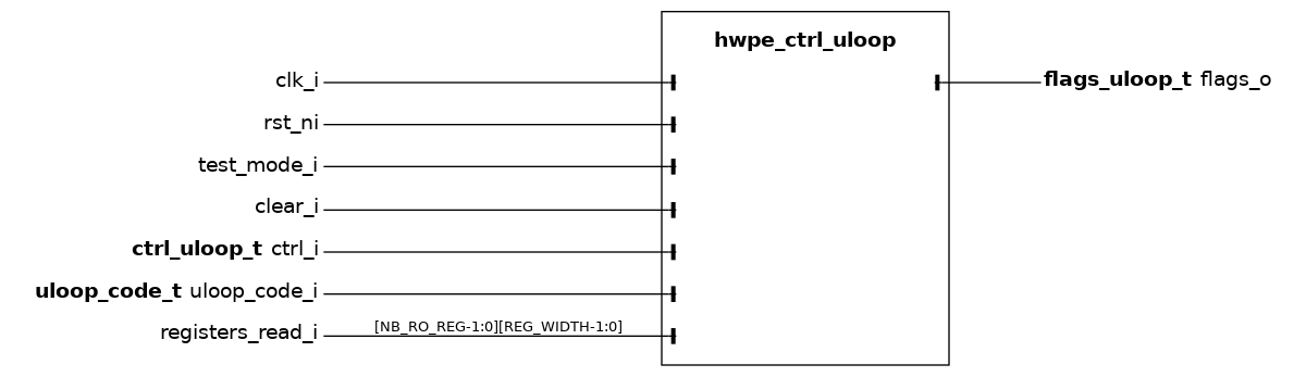
The hwpe_ctrl_uloop (micro-loop processor) module implements a very simple microcode processor that can be used to execute the main computation block of an HWPE multiple times according to a set of nested loops, while updating a handful of architectural state registers between iterations. These registers are typically used to generate base offsets that are forwarded to the HWPE address generators to walk through tensors larger than what is described in a single job.
The microcode processor implements NB_LOOPS nested loops (default 6). The innermost loop is loop 0, then loop 1, and so on. The number of iterations of each loop is configured at runtime through the ctrl_i.range field of uloop_code_i. After every iteration of any loop, the processor executes the sequence of operations associated to that loop (its body), then starts/continues the next inner loop; once the innermost loop completes, control returns to the next outer loop. When the outermost loop has executed its last iteration the flags_o.done signal is asserted.
The architectural state is a register file with two sections:
- NB_REG R/W registers (default 4) of width REG_WIDTH (default 32 bit).
These can be both the destination RA and the source RB of a uloop instruction. Their value is exposed to the outside on flags_o.offs and is typically used as a base offset to feed the HWPE address generators.
- NB_RO_REG read-only registers (default 12, max 32) provided
externally via registers_read_i. These can only be used as the RB source operand and are typically programmed once per job (e.g. through job-independent registers) to encode tensor strides, sizes, etc.
The microcode supports two instructions:
- add (op_sel=1): performs
RA := RA + RB(RA is one of the R/W registers, RB is any register).
mv (op_sel=0): performs RA := RB.
Each bytecode word (uloop_bytecode_t) is 11 bits wide and packs together op_sel (1 bit), a (5 bits, selects RA) and b (5 bits, selects RB). All operation words of all loop bodies are concatenated into a single code array of up to LENGTH entries (default 32). A separate uloop_loops_t per-loop header (9 bits: 5 bits uloop_addr + 4 bits nb_ops) tells the processor where each loop body starts in the code array and how many operations it contains.
The microcode is normally specified at a high level as a YAML file (see uloop-example/code.yml in the hwpe-ctrl repository) and compiled into the two bit fields (code + loops) by the uloop_compile.py Python helper. The resulting bit fields are typically either hardwired inside an HWPE wrapper or programmed at runtime through job-independent registers.
Example YAML body (excerpt from uloop-example/code.yml):
loop_stream_inner: # innermost: for jj in range(0, nif/TP)
  - { op: add, a: W,       b: TPin }
  - { op: add, a: x,       b: TPin }
loop_filter_x:     # for k in range(0, fs)
  - { op: add, a: W,       b: TPin }
  - { op: add, a: x,       b: TPin }
loop_filter_y:     # for l in range(0, fs)
  - { op: add, a: W,       b: TPin }
  - { op: add, a: x,       b: x_iter }
loop_stream_outer: # for ii in range(0, nof/TP)
  - { op: add, a: W,       b: TPin }
  - { op: add, a: y,       b: TPout }
  - { op: mv,  a: x,       b: x_major }
Here W, x, y, x_major are mnemonics for R/W registers
(RA-eligible) while TPin, TPout, x_iter are mnemonics for
R/O registers programmed once per job; the compiler converts the
mnemonics into the right 5-bit indices and emits a single hex bit field
for the whole code array and a second one for the per-loop headers.
When SHADOWED is 1, the uloop is double-buffered: a shadow register latches the freshly-computed flags_o and exposes it externally as soon as the consumer (e.g. the controller FSM) asserts ctrl_i.enable, so that one set of indices/offsets can be consumed while the next is being computed.
Name |
Type |
Description |
done |
logic |
1 when the outermost loop has completed all its iterations. |
valid |
logic |
1 when offs / idx hold a freshly-computed set of values. |
ready |
logic |
1 when the uloop can accept a new ctrl_i.enable pulse. |
offs |
logic [NB_REG-1:0][REG_WIDTH-1:0] |
Current value of each R/W register (typical streamer offsets). |
idx |
logic [NB_LOOPS-1:0][CNT_WIDTH-1:0] |
Current iteration counter of each loop. |
idx_update |
logic [NB_LOOPS-1:0] |
1 for each loop whose iteration index just changed. |
loop |
logic [$clog2(NB_LOOPS)-1:0] |
Index of the loop whose body was executed last. |
hwpe_ctrl_seq_mult#
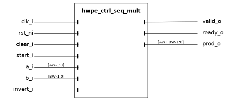
The hwpe_ctrl_seq_mult module is a utility module that implements a fully sequential unsigned multiplier of two operands a_i (of width AW) and b_i (of width BW). It is typically used to compute derivative parameters used by the microcode processor hwpe_ctrl_uloop (e.g. a stride value obtained as the product of two job-independent registers) without dedicating a fast combinational multiplier to that purpose.
Operation is started by asserting the start_i strobe for one cycle. The operands a_i and b_i must be kept stable for AW-1 cycles after start_i; the product appears on prod_o and valid_o is asserted high for one cycle when the product has been computed. The ready_o output is high when the multiplier is idle and ready to accept a new operation. When invert_i is asserted, an extra cycle is taken to two’s-complement-negate the result (i.e. the product is -(a_i*b_i) rather than a_i*b_i).
Name |
Default |
Description |
AW |
8 |
Width of operand a_i and number of iteration cycles. |
BW |
8 |
Width of operand b_i. The product has width AW+BW. |